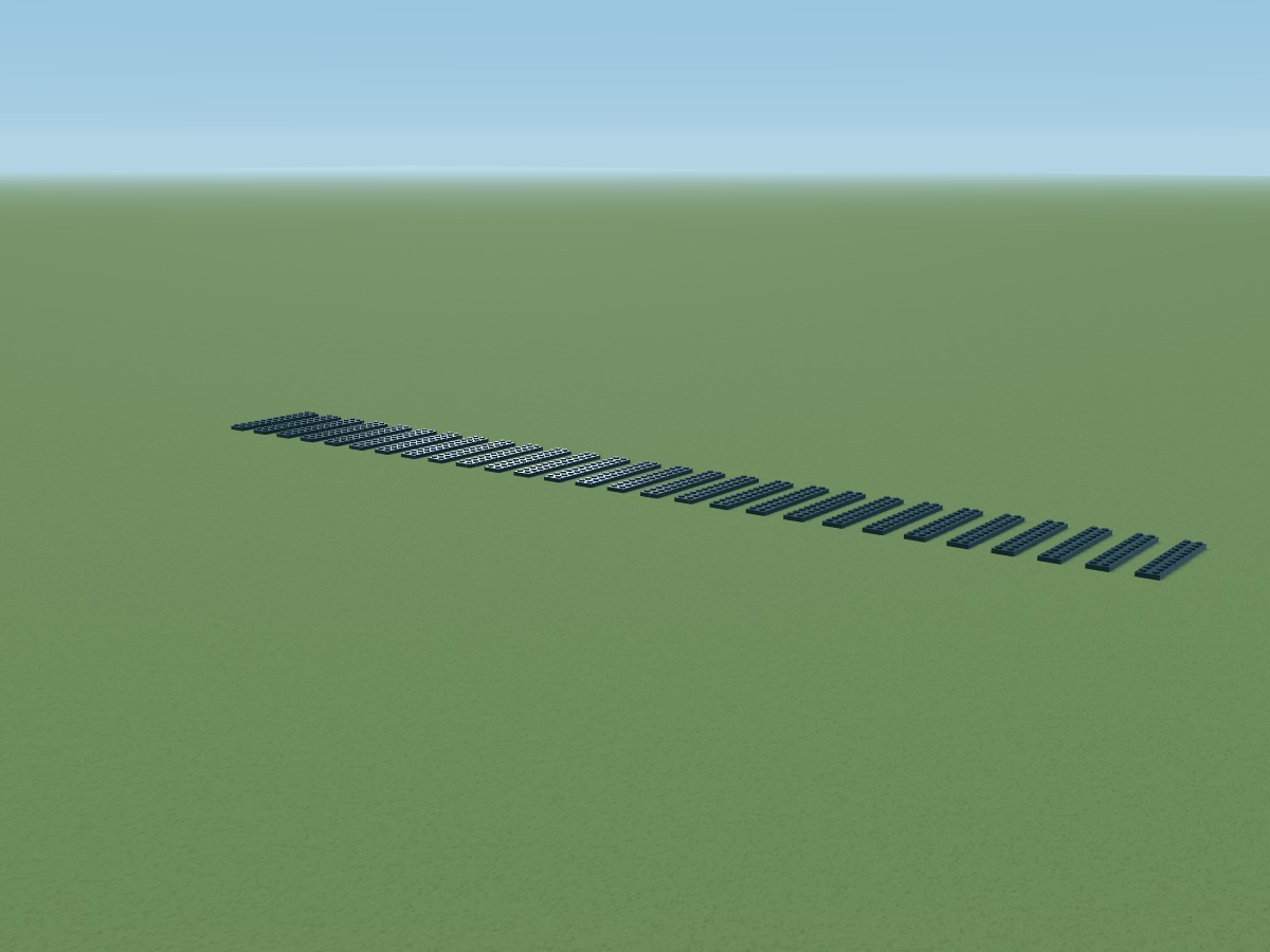
01 · Track sleepers
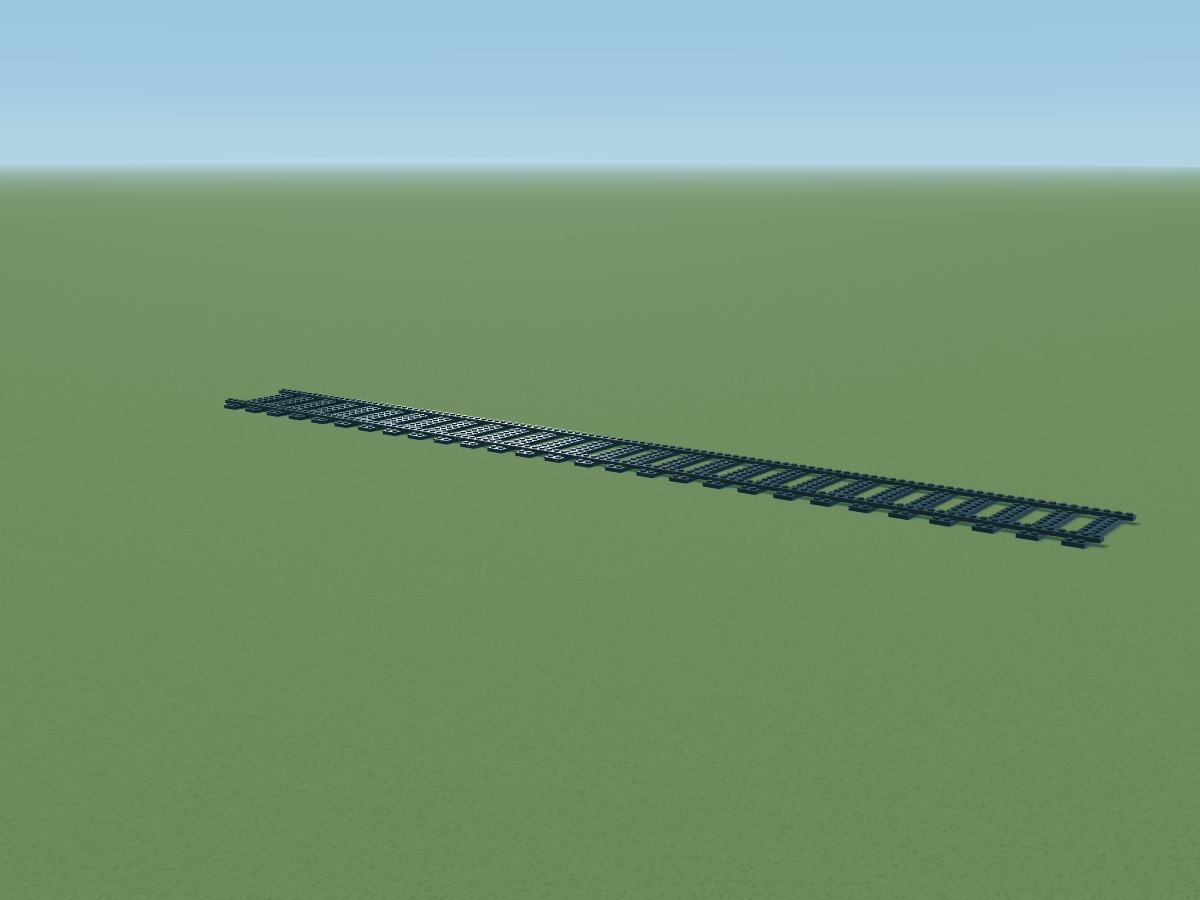
Arrange black sleepers across 112 studs. This display track is built from plates.
 BRICK
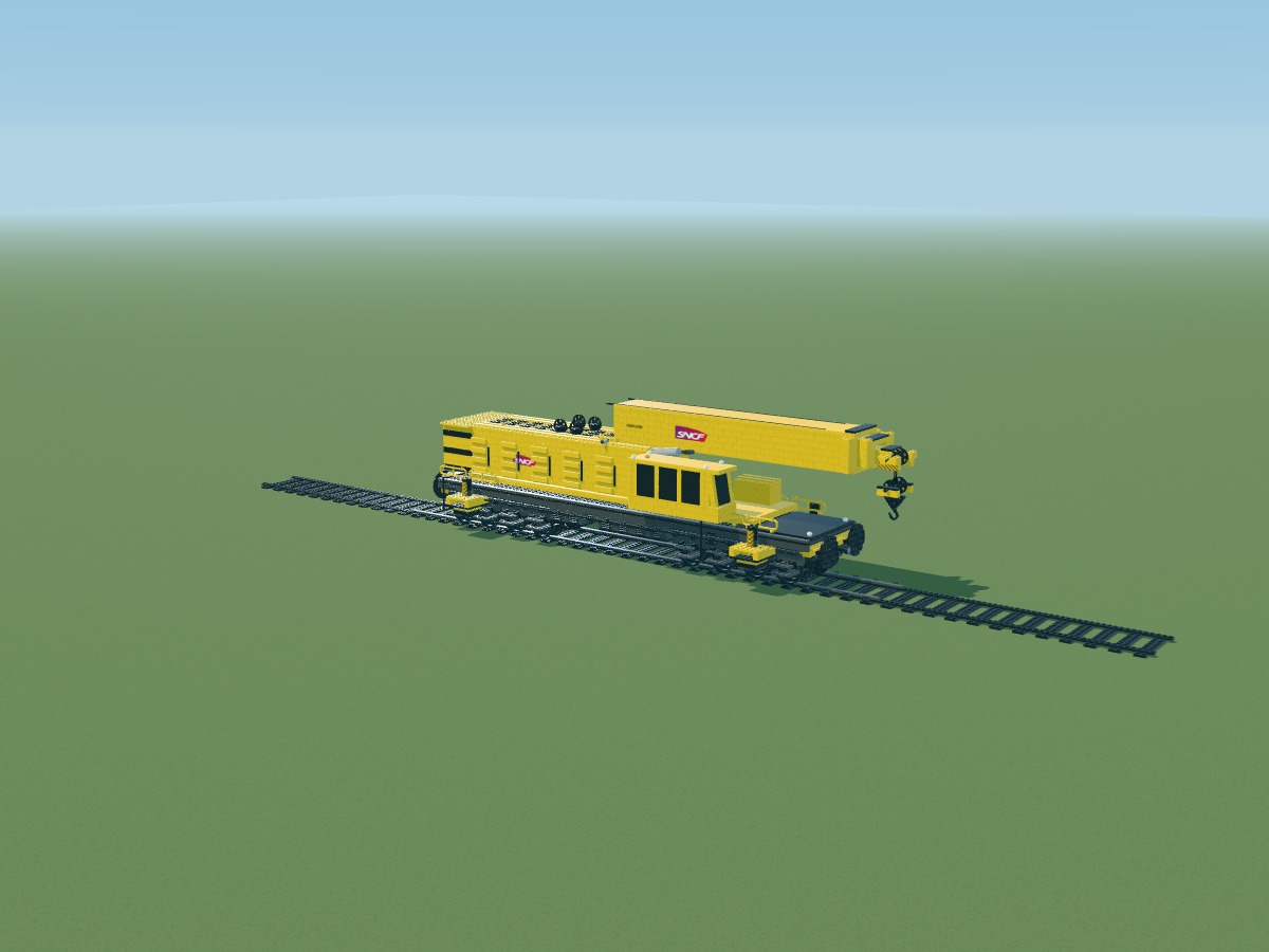
BRICKThe same love of railways, more room for the details. A second interpretation of the SNCF crane, shaped around its offset cab, eight axles and telescopic boom.
A creation by Nicolas Pieper
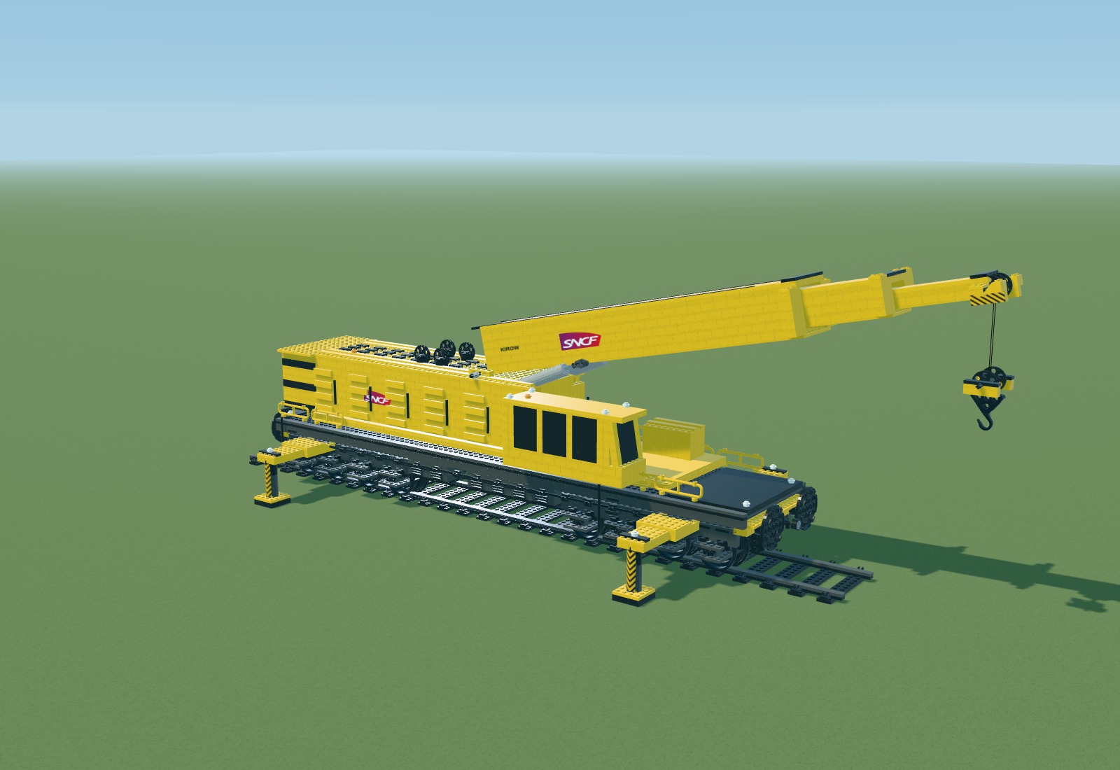
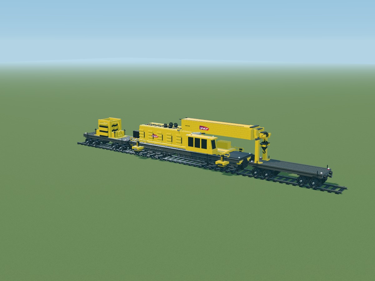
Still view of the complete model
Activate 3D, then adjust the crane or choose a pose.
Drag with a mouse or finger to orbit, scroll or pinch to zoom. The controls are also available with a keyboard.
The movements illustrate the digital model’s intended operation. They do not validate its connections or lifting capacity.
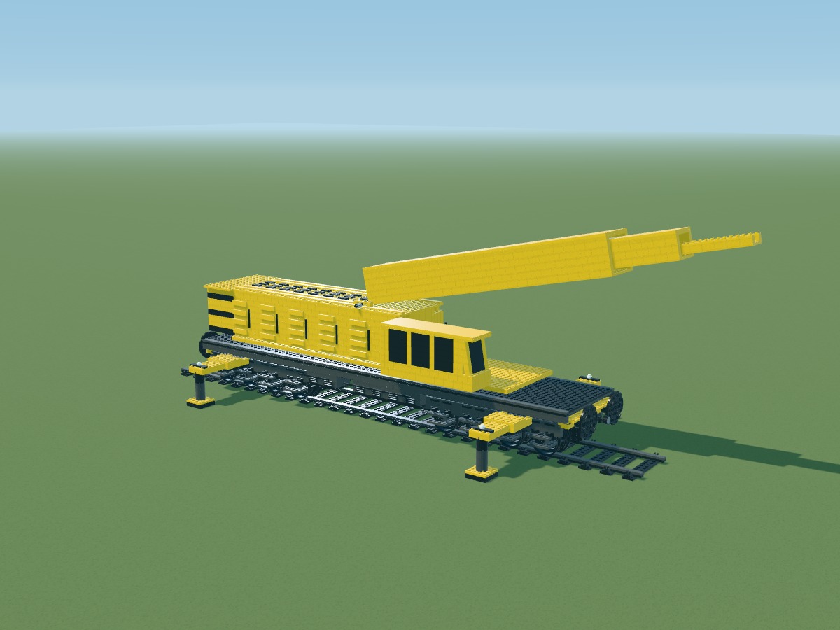
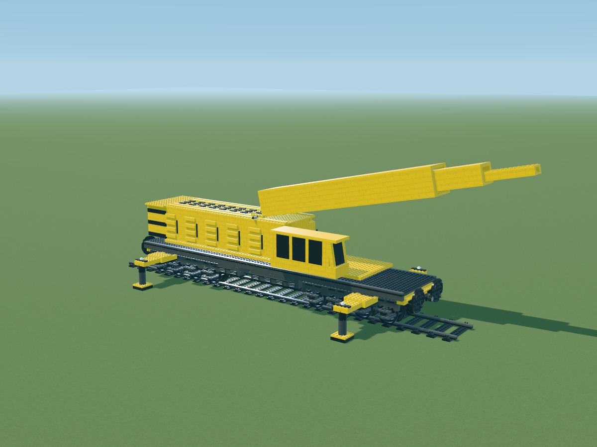
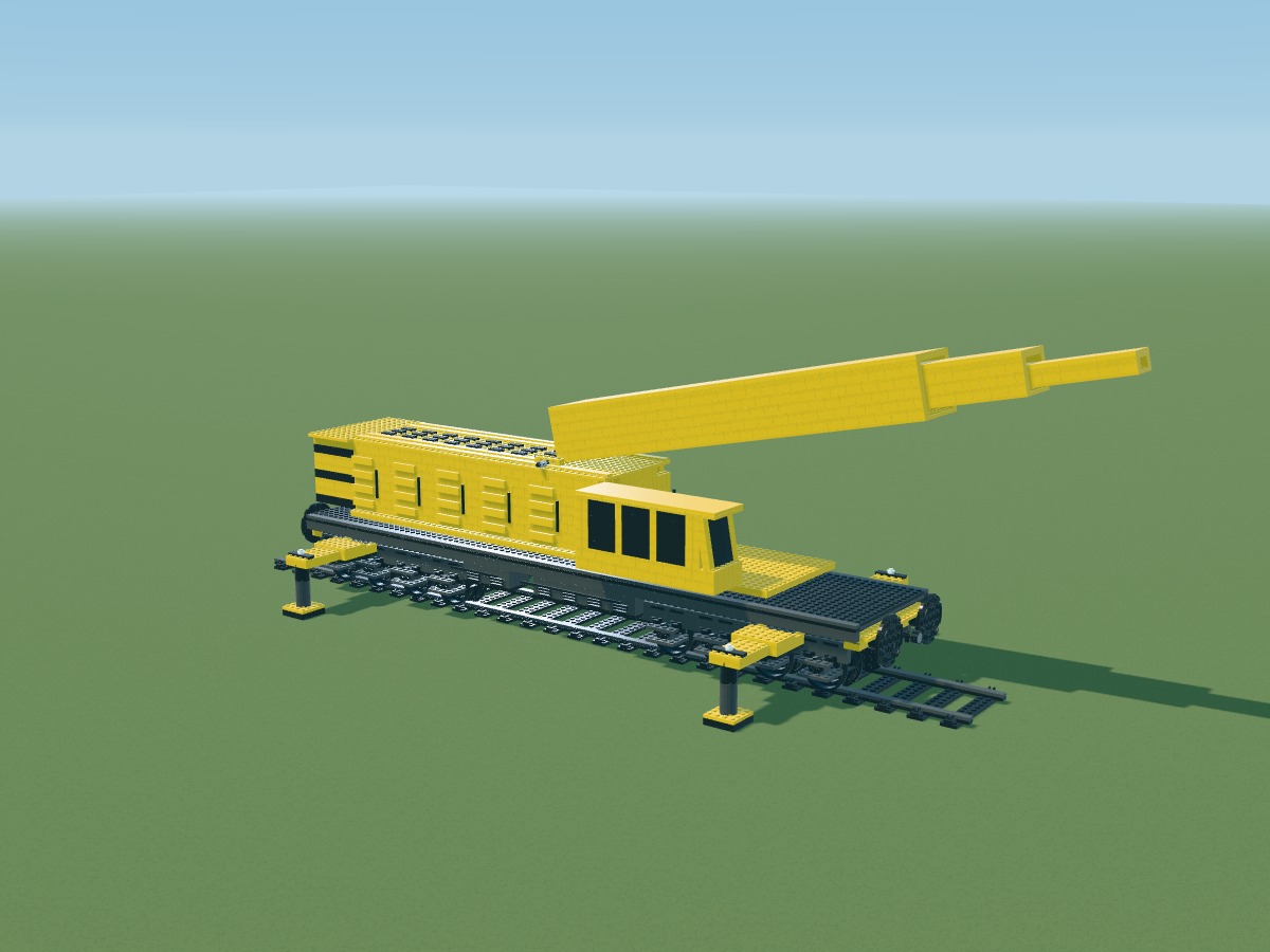
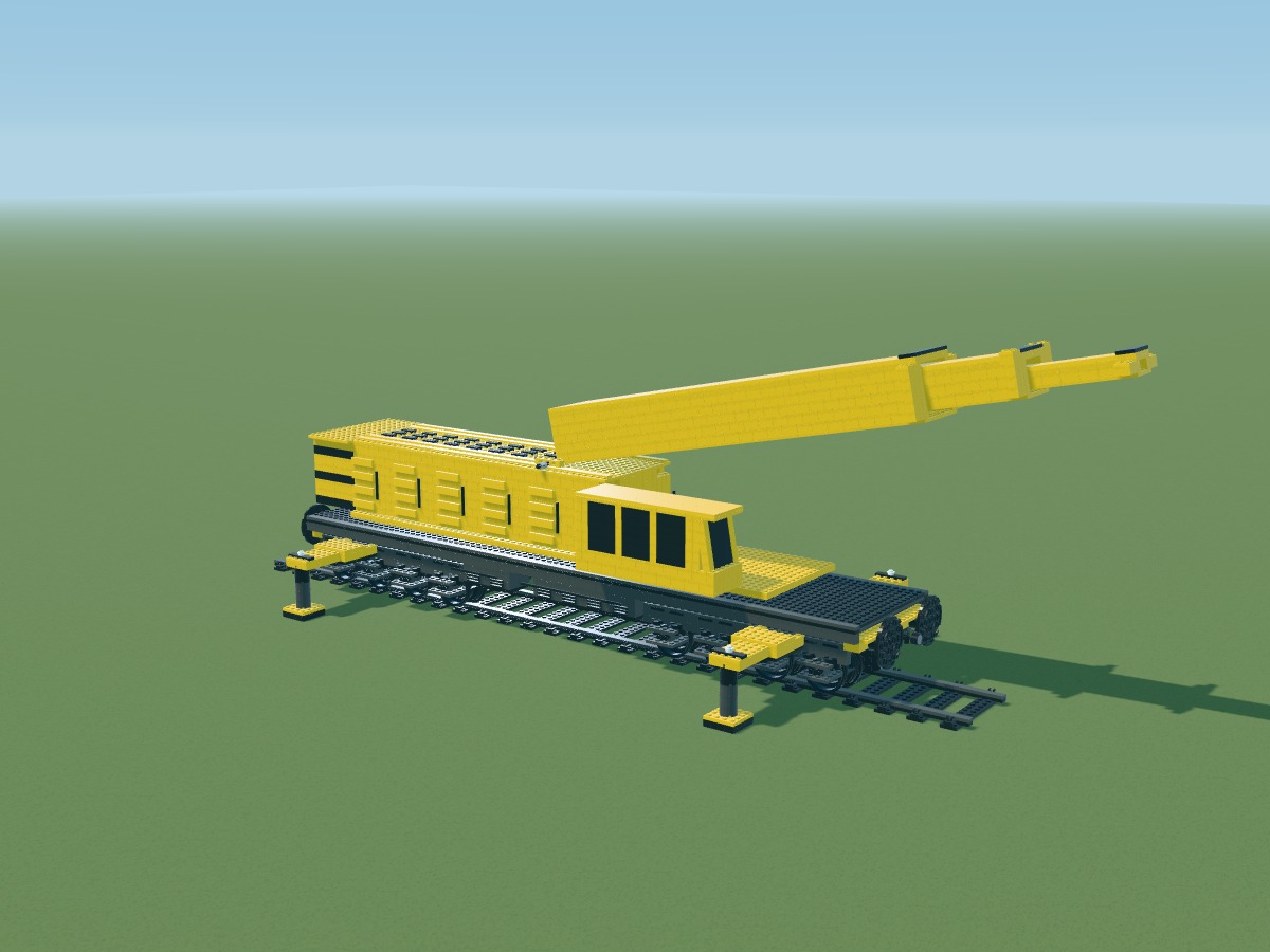
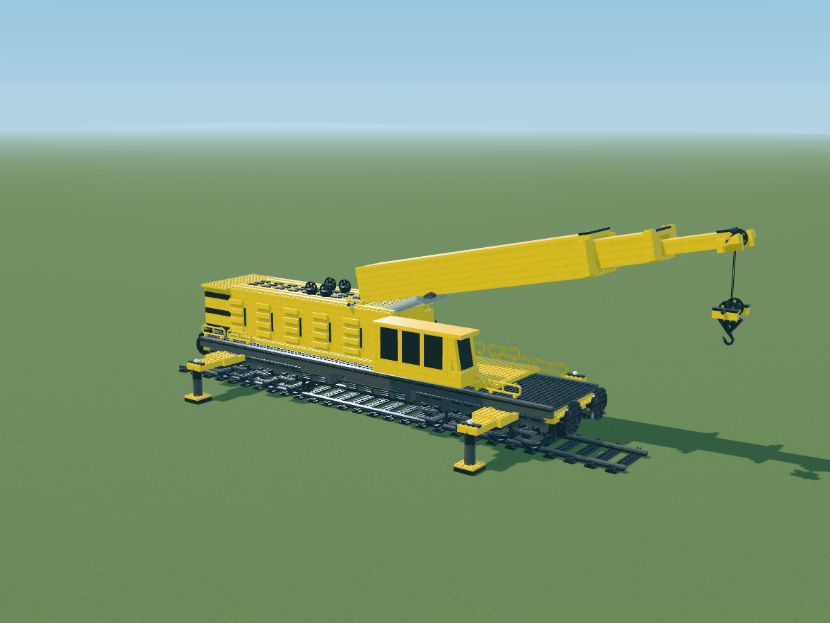
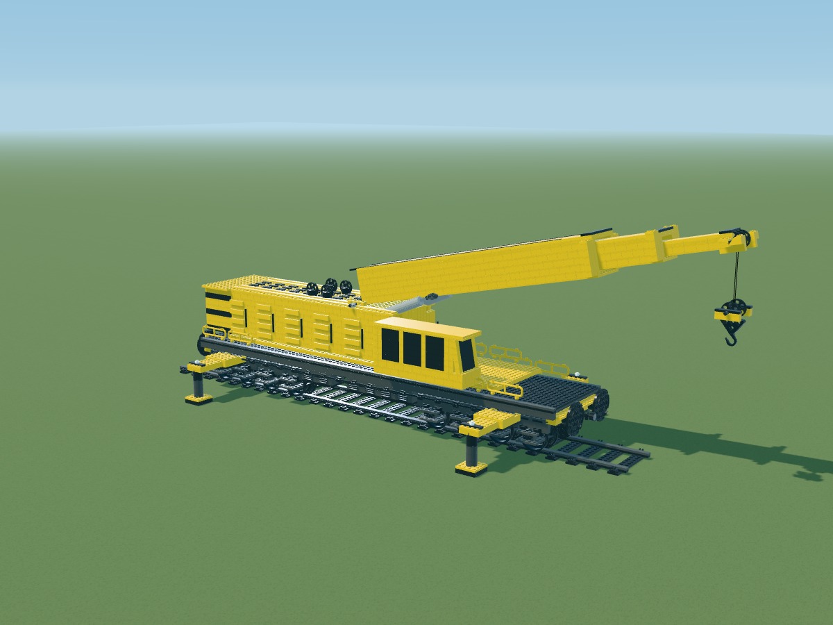
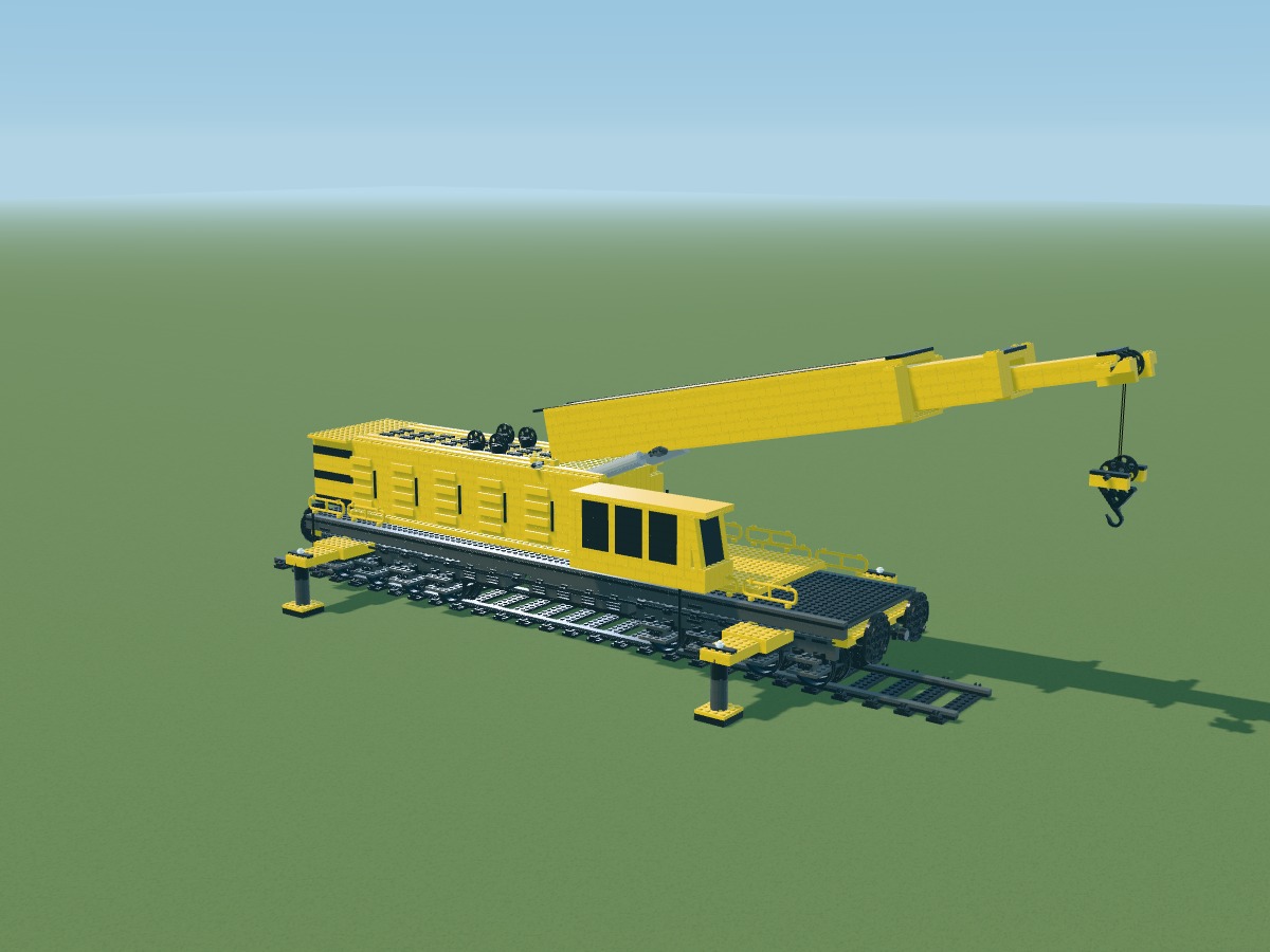
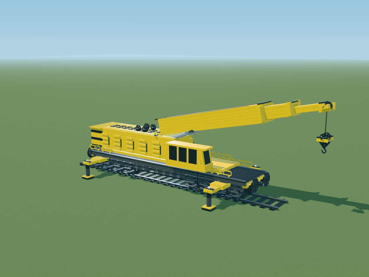
A cab on one side, equipment on the other, a low chassis beneath a long boom: the real machine’s proportions guide this version.
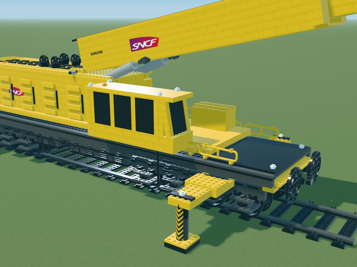
The glazed cab and equipment compartment occupy distinct volumes. Walkways, handrails and the counterweight define the superstructure.
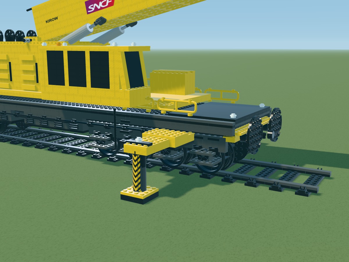
Two four-axle bogies recreate the railway silhouette. Buffers, end beams and outriggers give the underframe its width.
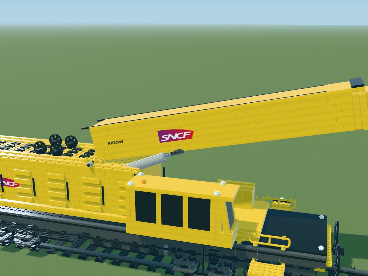
Two slimmer sections extend the main boom. Twin lifting actuators, the boom head and hook block make the mechanism easier to read.
One wagon beneath the boom, another behind the crane: the transport configuration takes its cue from the train in the supplied photographs.
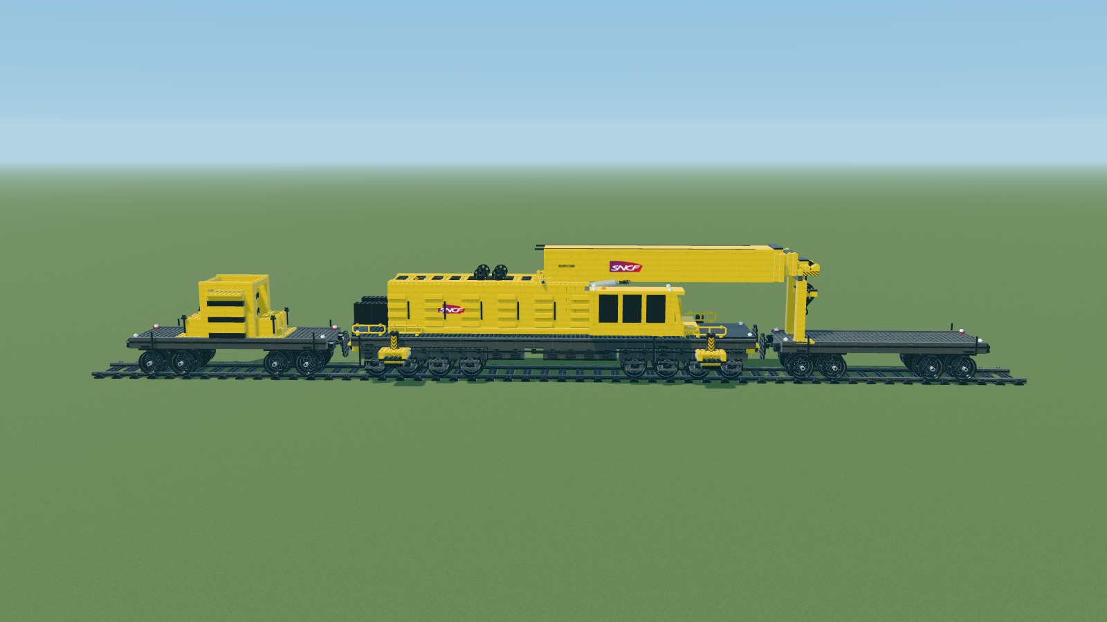
Working mode shows the crane alone on its track. Transport mode lowers the boom and adds two accompanying wagons. This train is a digital interpretation; its couplings and physical operation still need validation.
| Assembly | Pieces |
|---|---|
| Crane and display track | 4,822 |
| Transport additions: two wagons and extra track | 931 |
| Complete inventory for both modes | 5,753 |
The headline count covers the crane and its track. The CSV, LDraw model and illustrated guide cover the complete train; shared pieces are counted only once.
In its 8 April 2026 press release, SNCF Réseau describes a Kirow crane brought from Dijon for a railway operation. The figures below refer to that real machine.
Read the SNCF Réseau press release (PDF)This model is a visual interpretation. Those figures do not define a certified scale or the model’s capabilities.
The illustrations, parts added at each step and complete inventory describe the same digital model.
 107 of 107
Finish with handles and chocks. Transport elements are counted separately from the crane.
Parts added at this step
Digital study based on public photographs. Approximate 1:20 scale based on an 88-stud chassis. Parts retain their real dimensions; connections, slides, actuators, cable and stability have not been tested with a physical prototype. The black window panels are opaque, matching the catalogue variant used. Markings are custom graphics. The display track and both accompanying wagons are included in the complete inventory. The visible cable is an unlisted simulation guide.
Arrange black sleepers across 112 studs. This display track is built from plates.
Positions belong to the digital model. Connections still require a physical prototype.
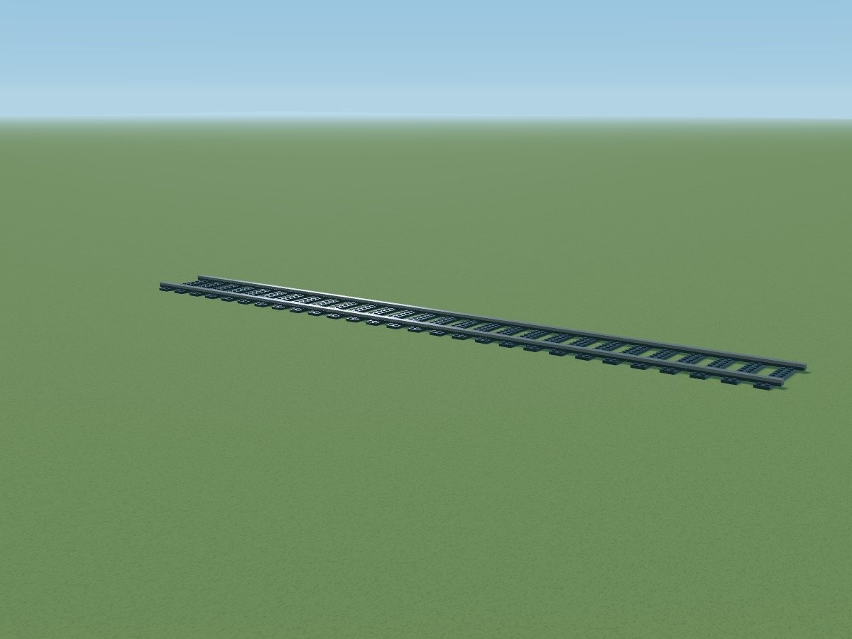
Positions belong to the digital model. Connections still require a physical prototype.
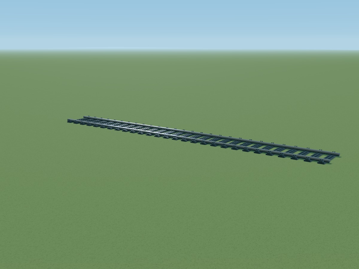
Positions belong to the digital model. Connections still require a physical prototype.
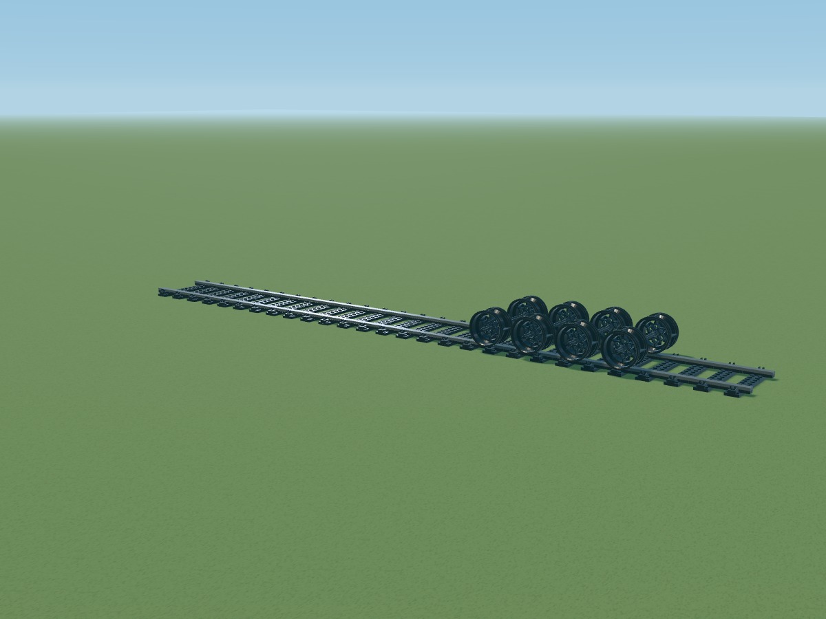
Four axles per bogie. Wheels 56908 and flanges 11213 are referenced parts; their combination remains experimental.
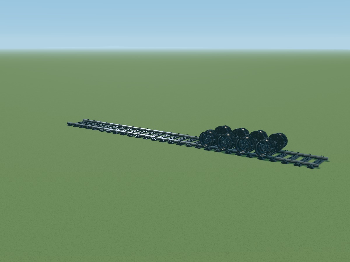
Positions belong to the digital model. Connections still require a physical prototype.
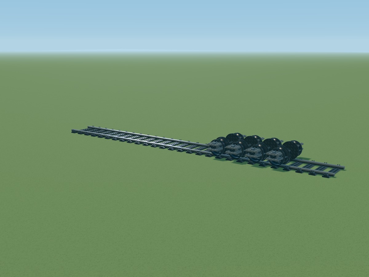
Positions belong to the digital model. Connections still require a physical prototype.
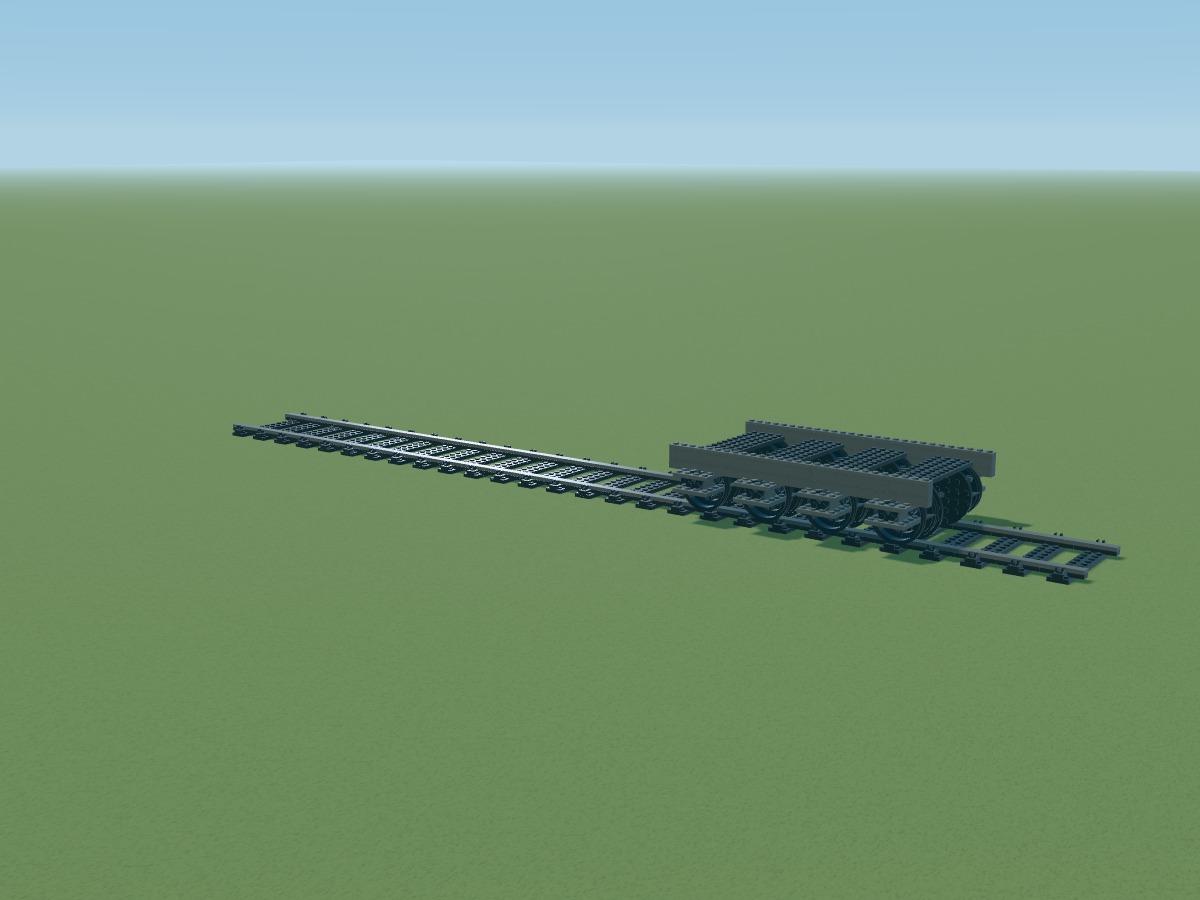
Positions belong to the digital model. Connections still require a physical prototype.
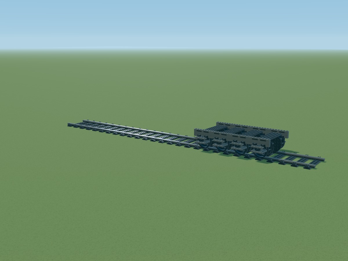
Positions belong to the digital model. Connections still require a physical prototype.
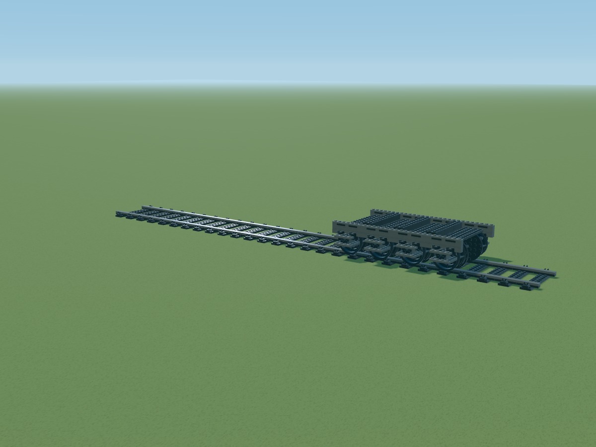
Positions belong to the digital model. Connections still require a physical prototype.
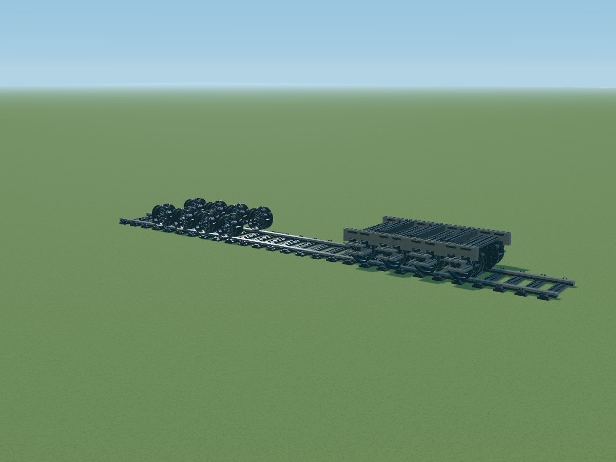
Four axles per bogie. Wheels 56908 and flanges 11213 are referenced parts; their combination remains experimental.
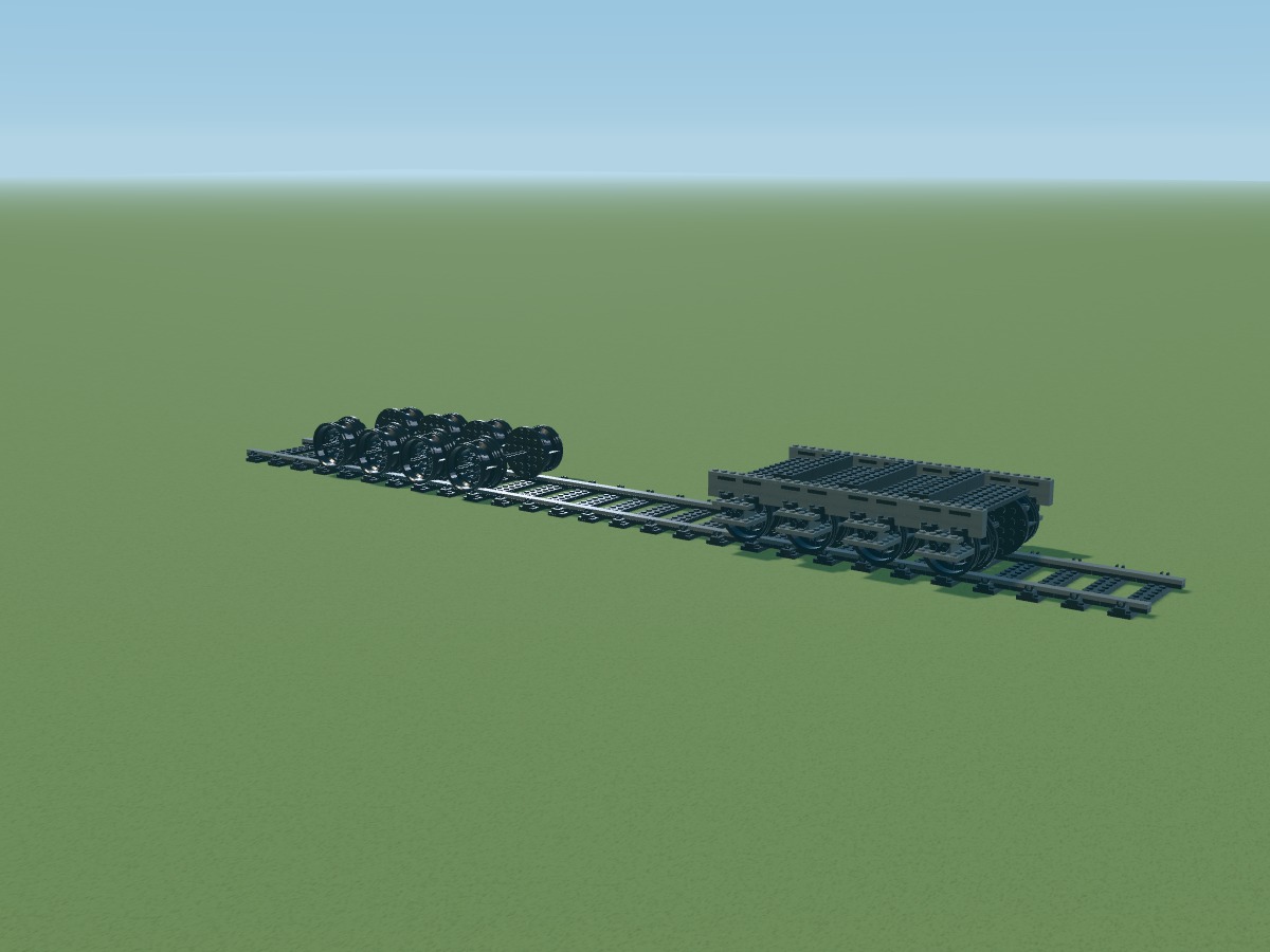
Positions belong to the digital model. Connections still require a physical prototype.
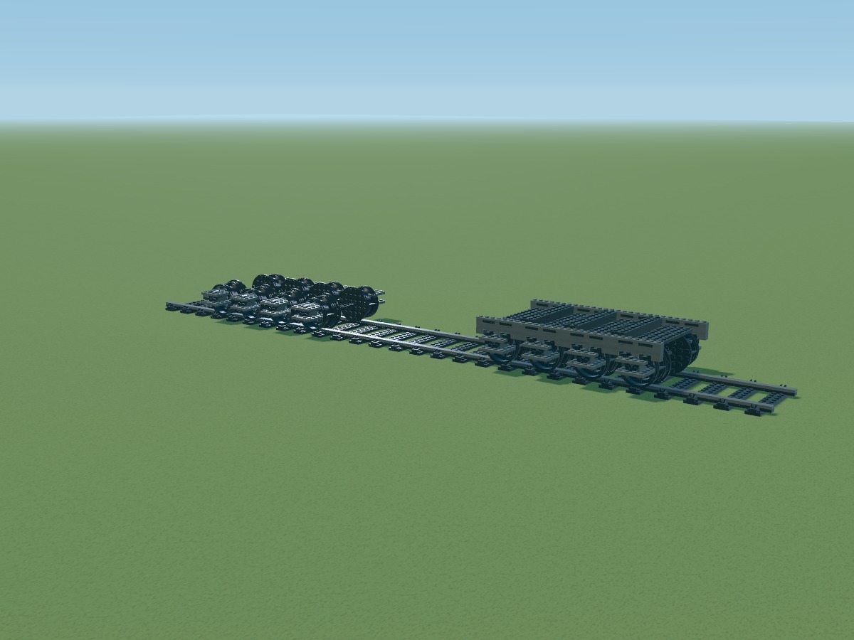
Positions belong to the digital model. Connections still require a physical prototype.
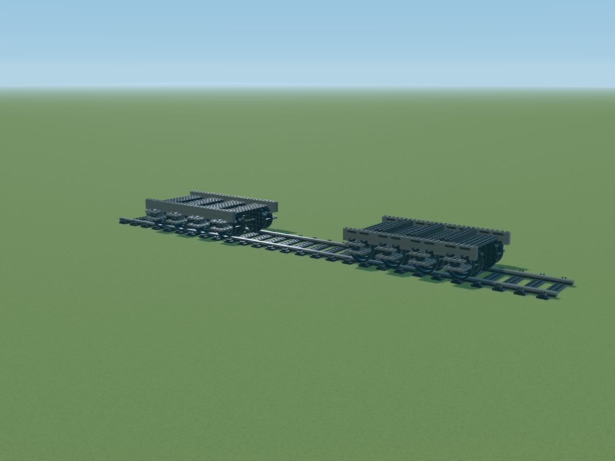
Positions belong to the digital model. Connections still require a physical prototype.
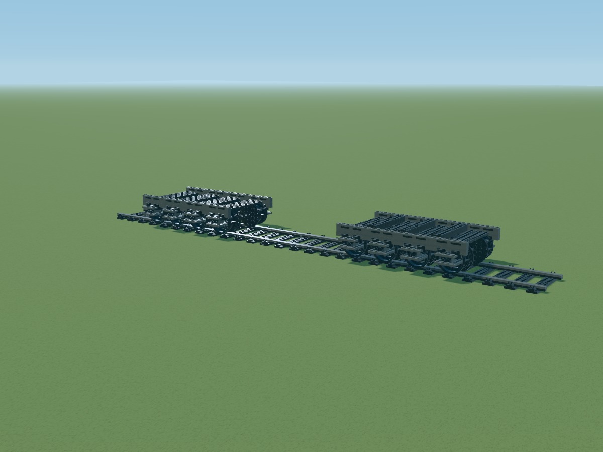
Positions belong to the digital model. Connections still require a physical prototype.
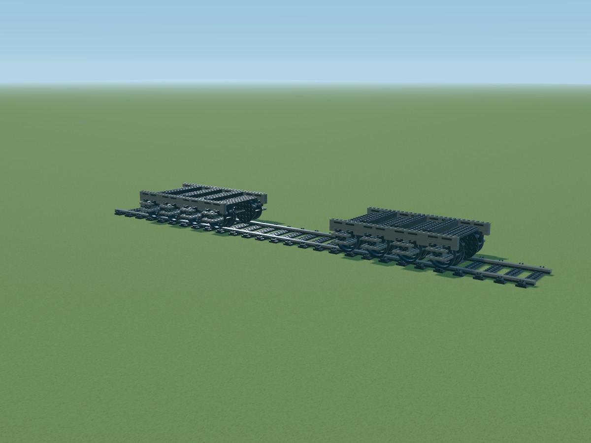
Positions belong to the digital model. Connections still require a physical prototype.
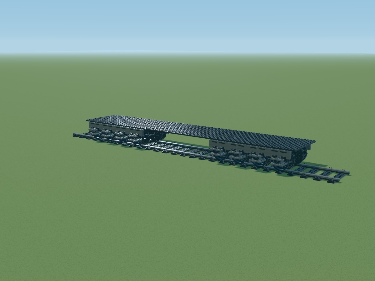
Positions belong to the digital model. Connections still require a physical prototype.
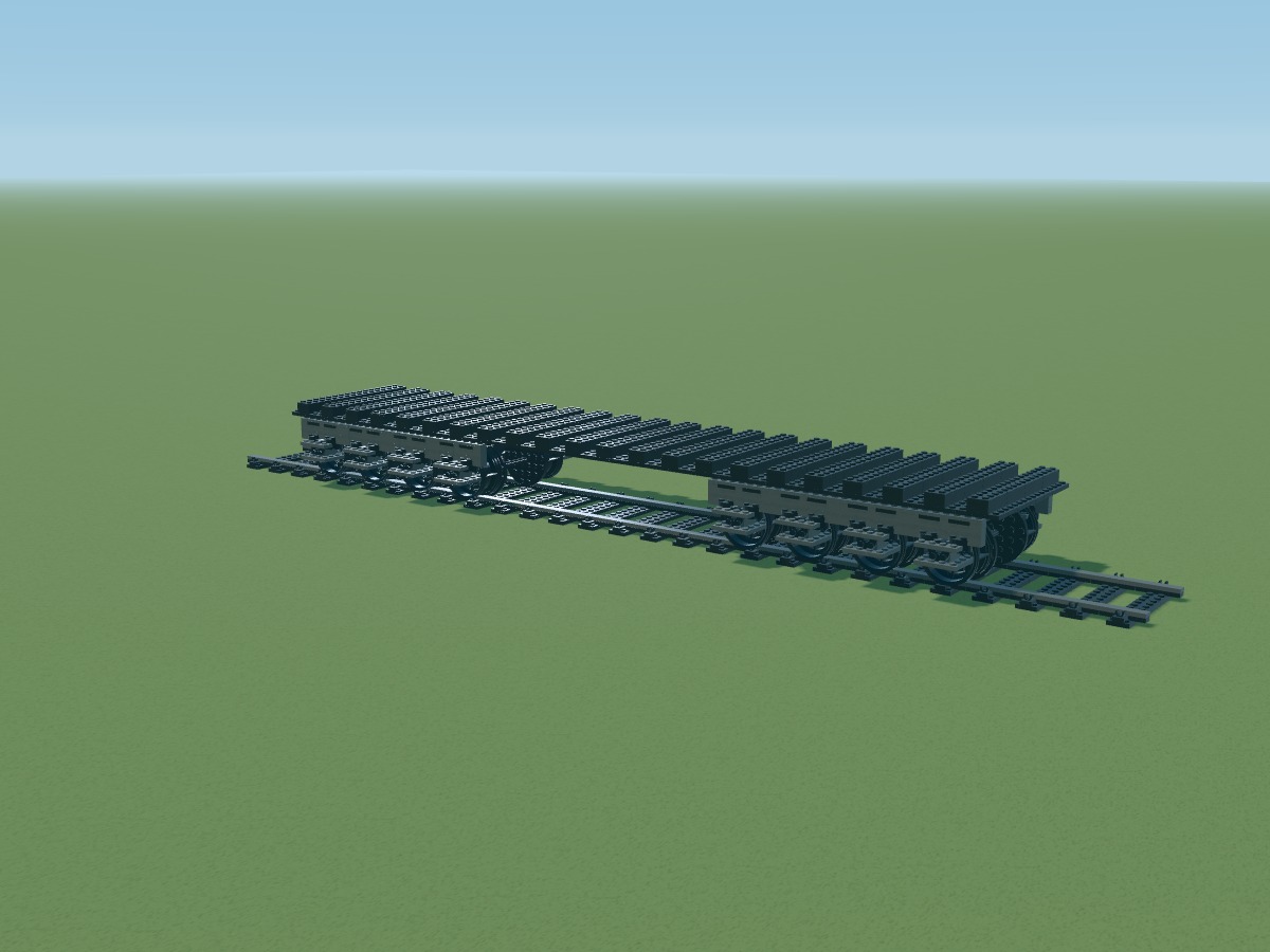
Positions belong to the digital model. Connections still require a physical prototype.
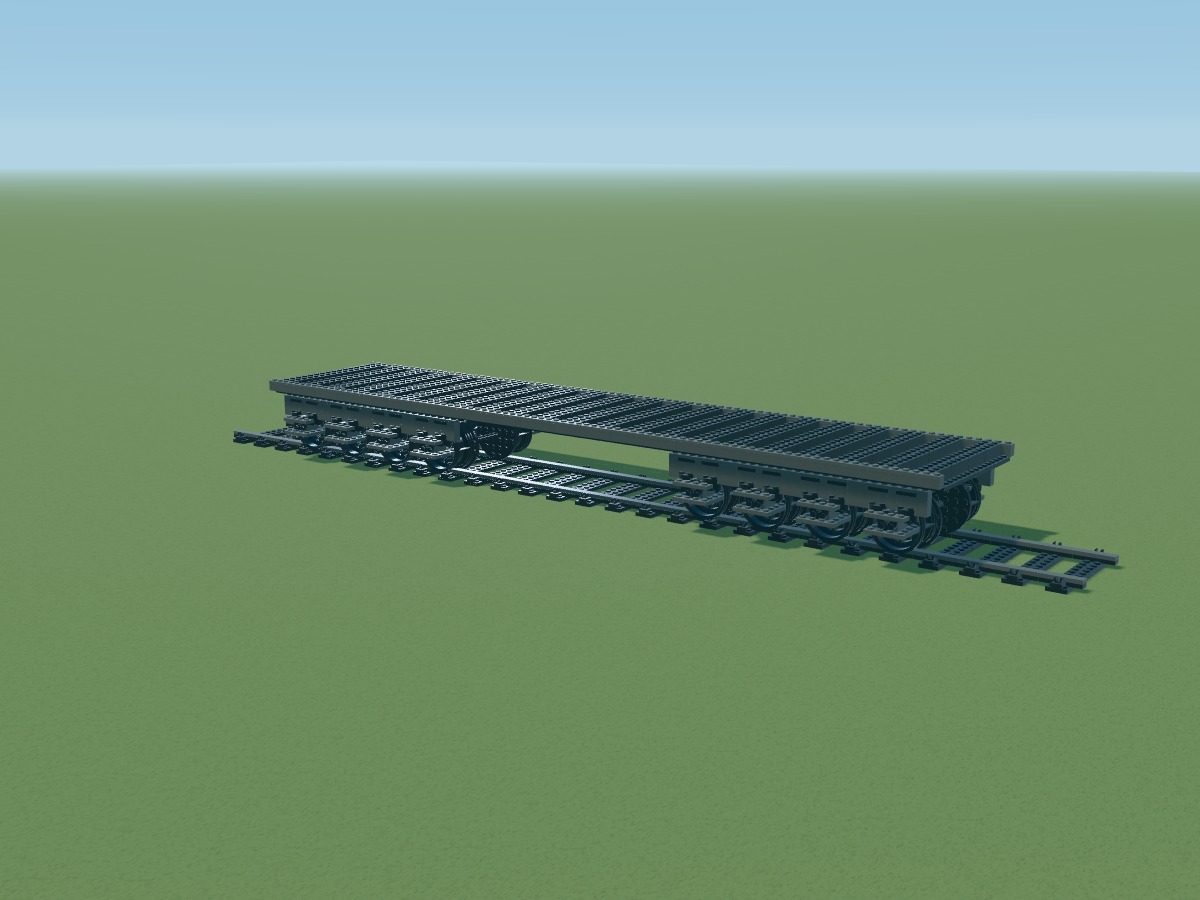
Positions belong to the digital model. Connections still require a physical prototype.
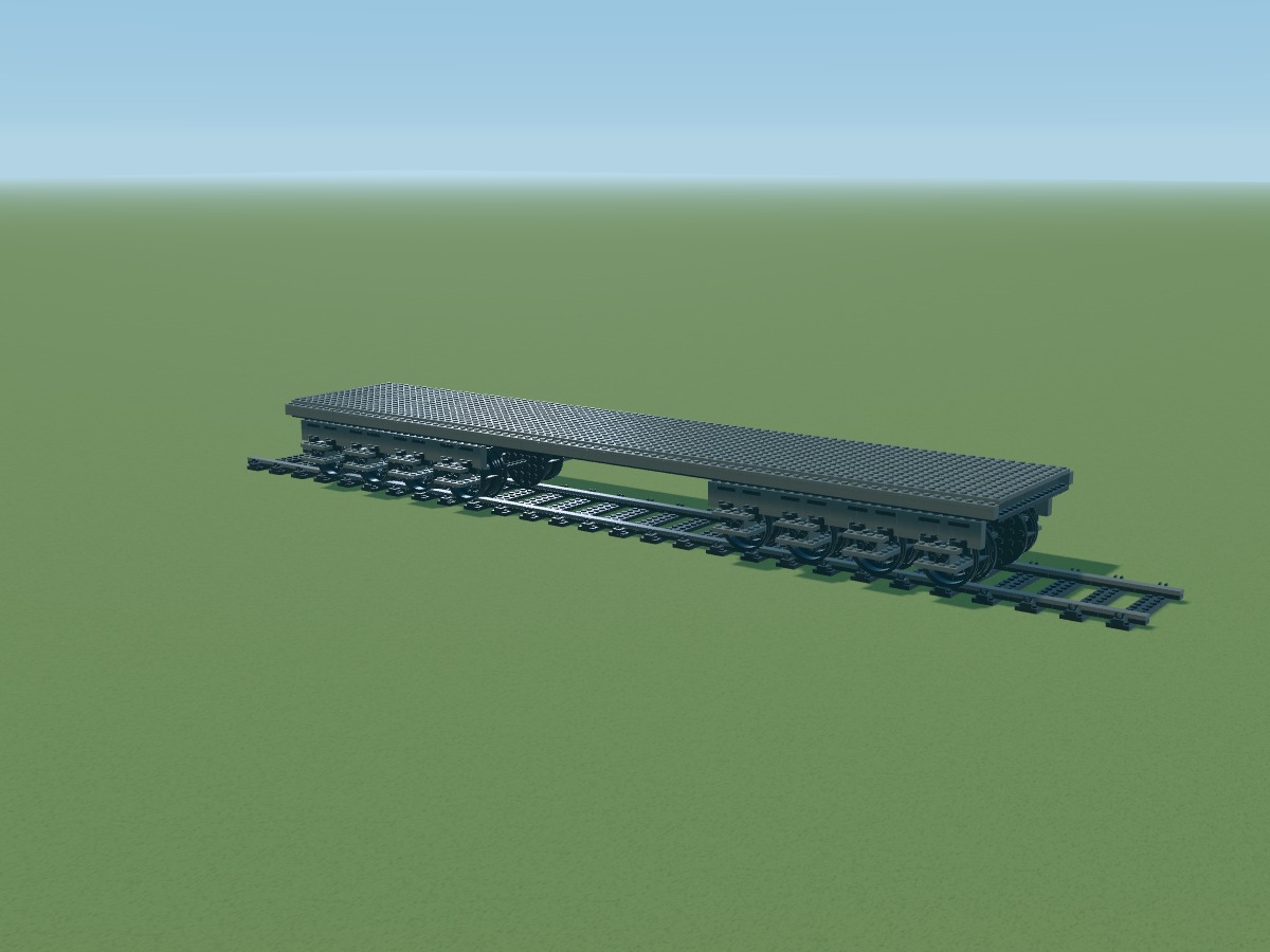
Positions belong to the digital model. Connections still require a physical prototype.
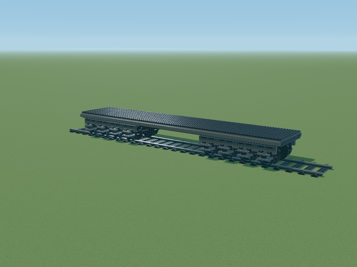
Positions belong to the digital model. Connections still require a physical prototype.
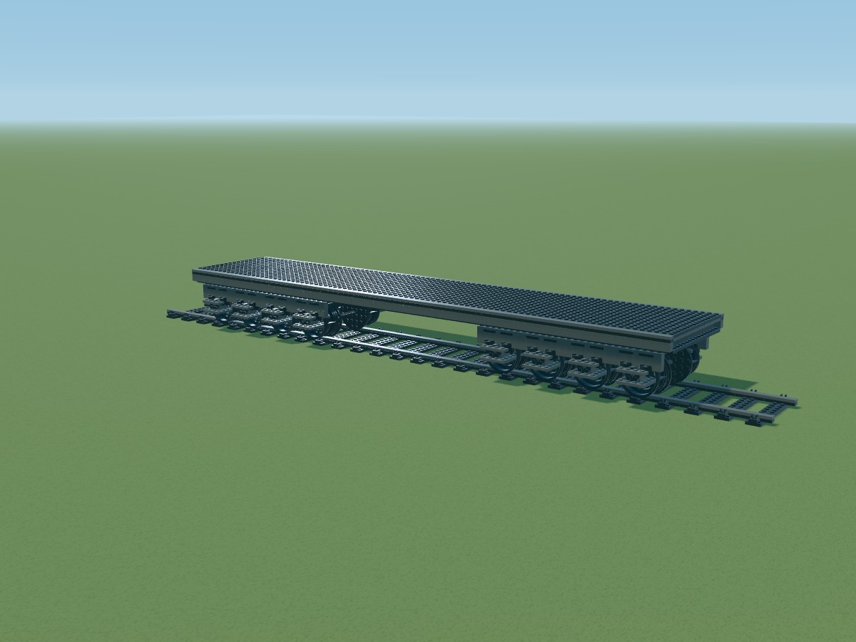
Positions belong to the digital model. Connections still require a physical prototype.
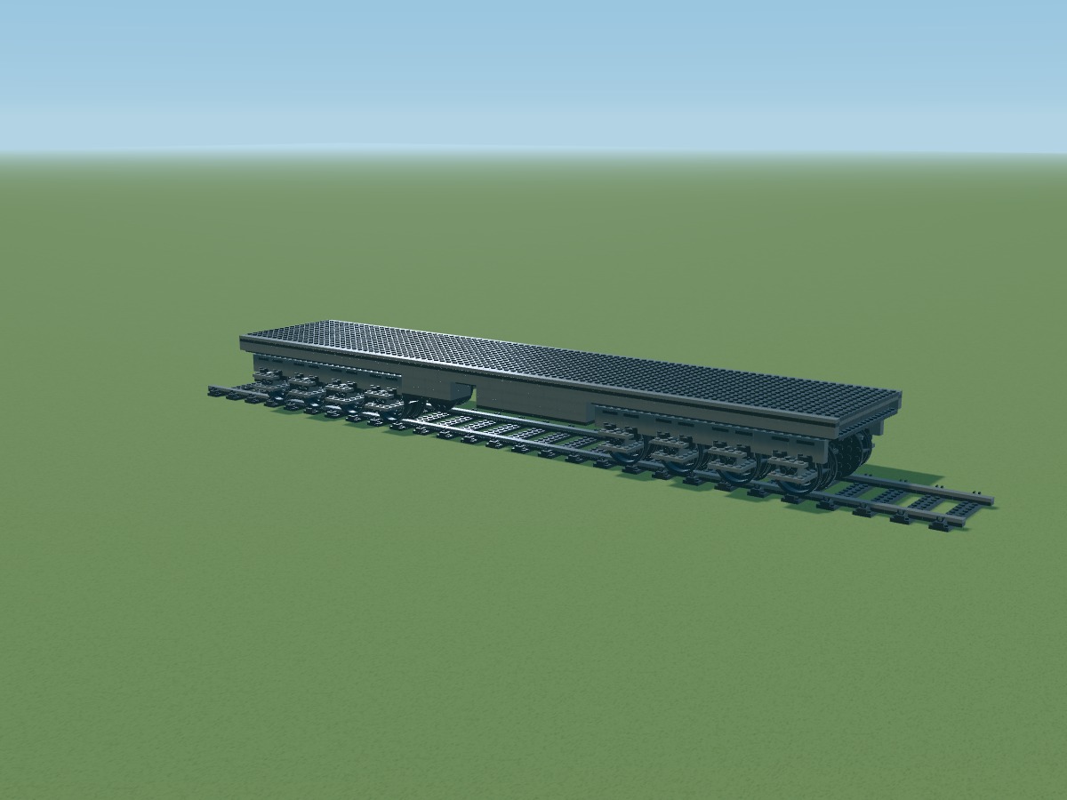
Positions belong to the digital model. Connections still require a physical prototype.
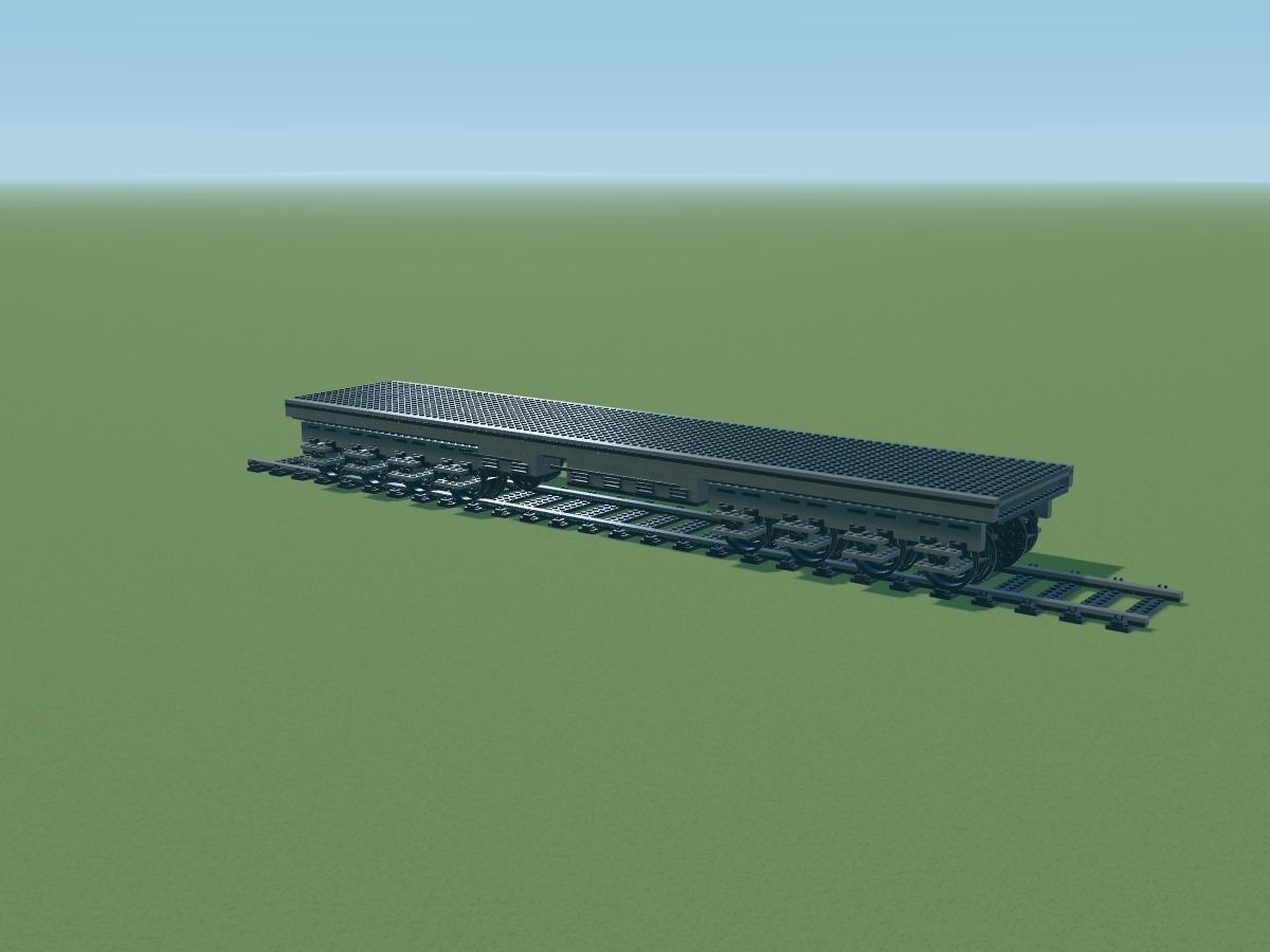
Positions belong to the digital model. Connections still require a physical prototype.
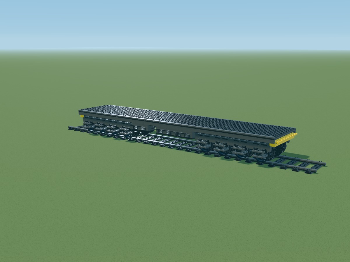
Positions belong to the digital model. Connections still require a physical prototype.
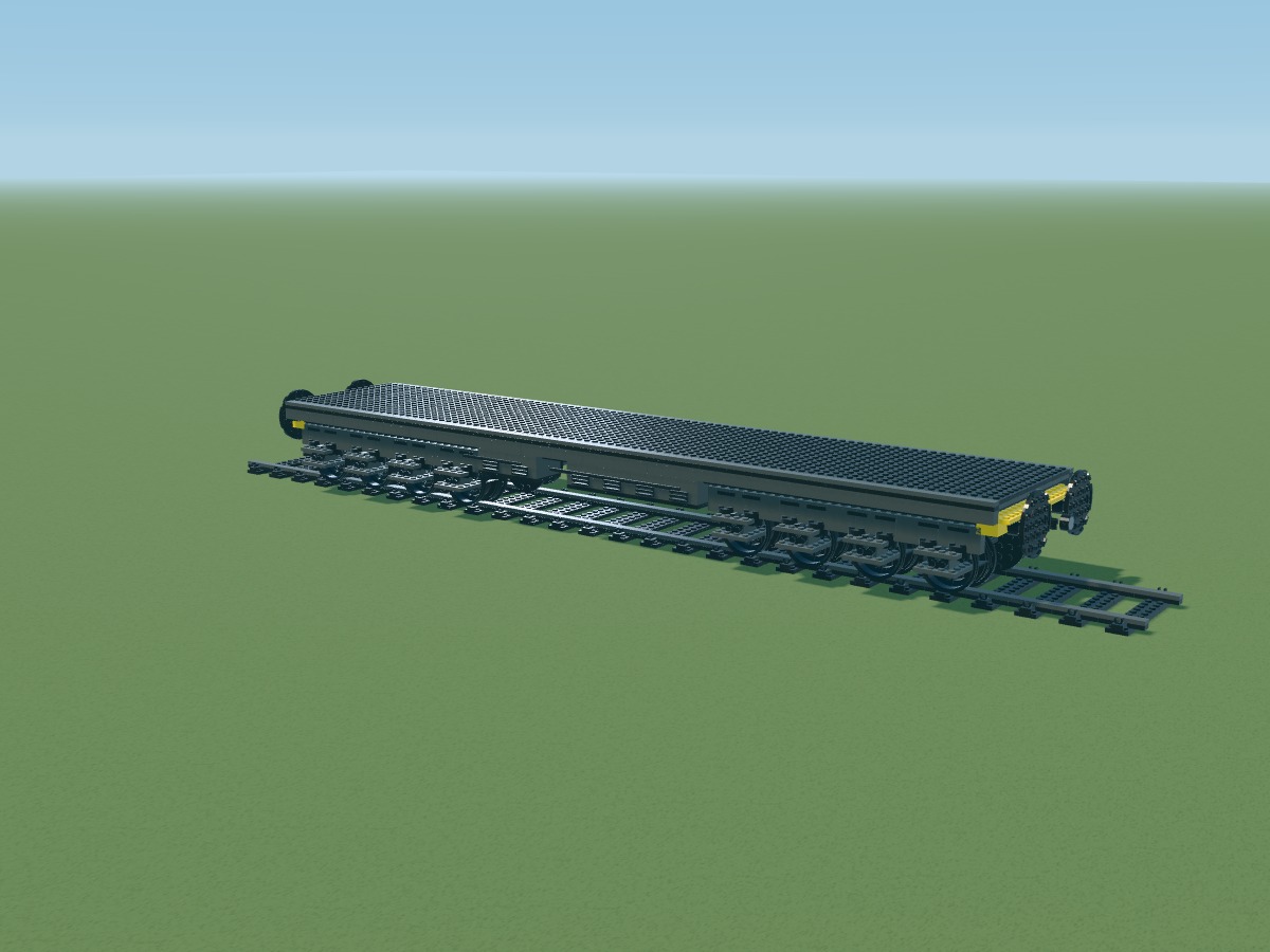
Positions belong to the digital model. Connections still require a physical prototype.
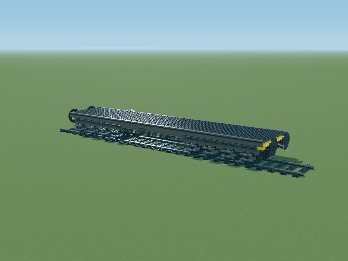
Arm, leg and pad stay together during digital motion. Stability and locking must be tested.
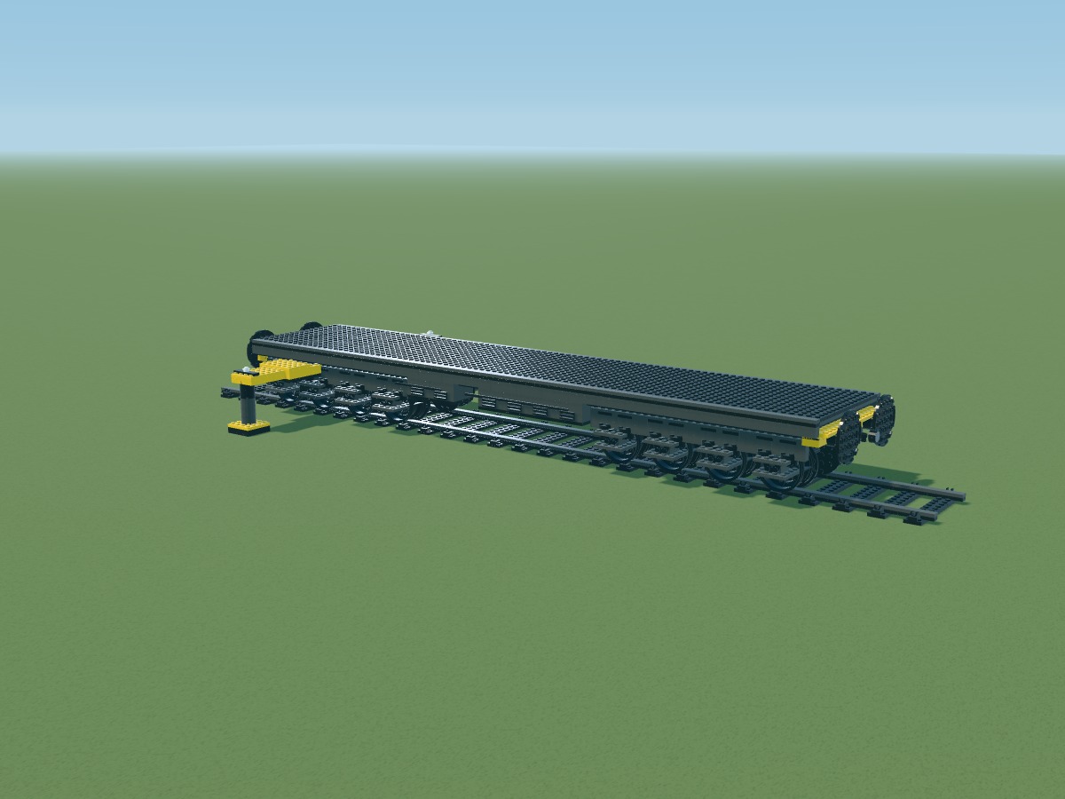
Arm, leg and pad stay together during digital motion. Stability and locking must be tested.
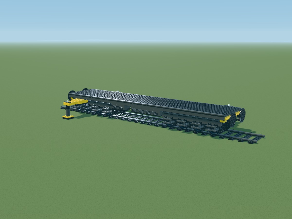
Arm, leg and pad stay together during digital motion. Stability and locking must be tested.
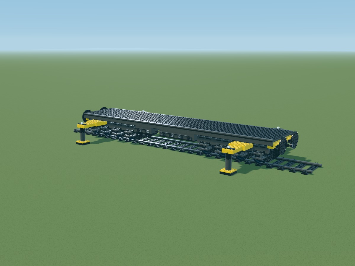
Arm, leg and pad stay together during digital motion. Stability and locking must be tested.
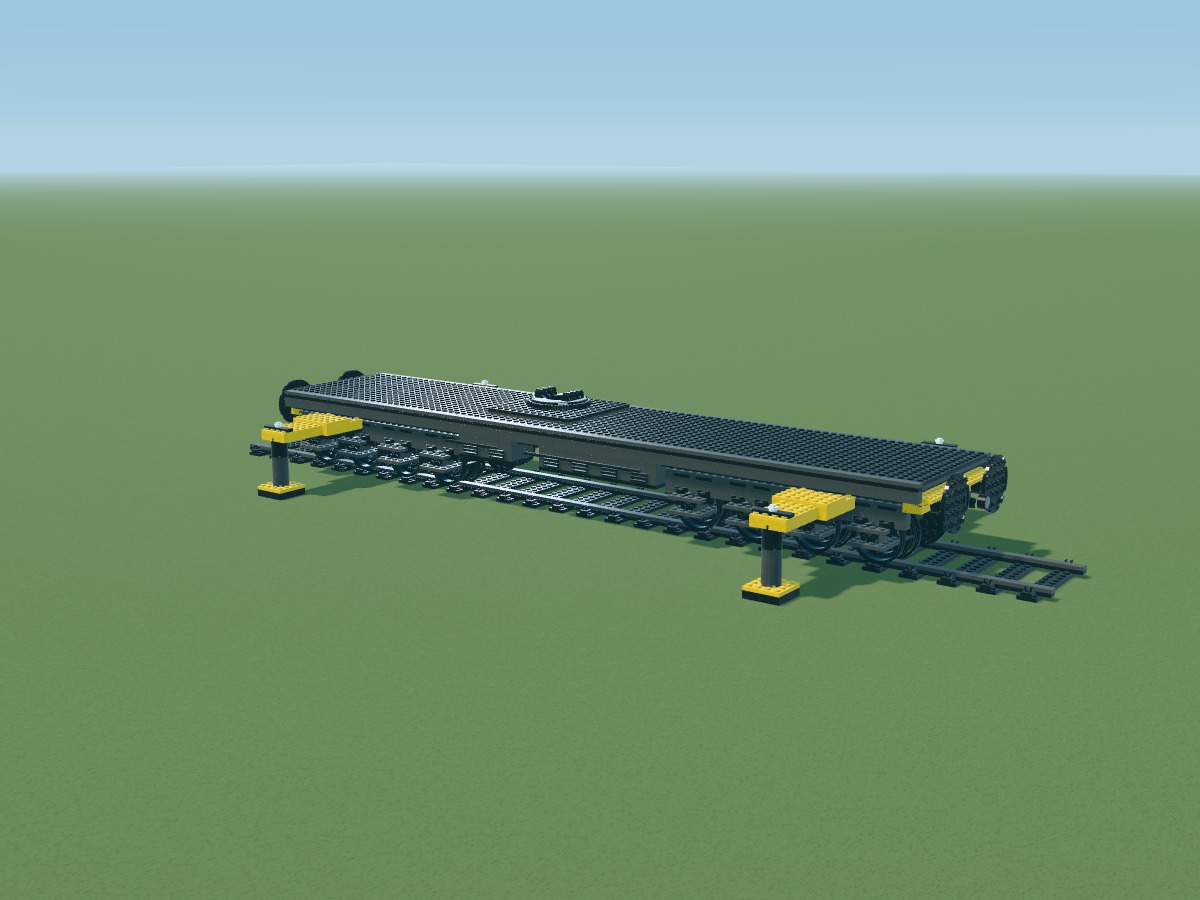
Positions belong to the digital model. Connections still require a physical prototype.
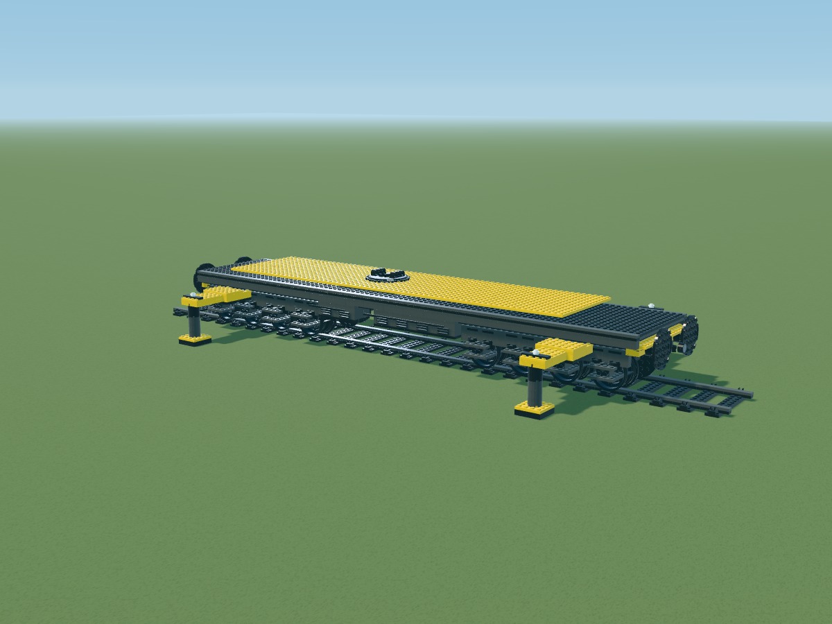
Positions belong to the digital model. Connections still require a physical prototype.
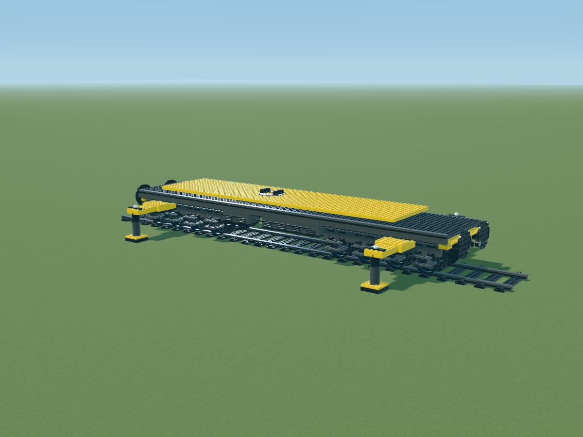
Positions belong to the digital model. Connections still require a physical prototype.
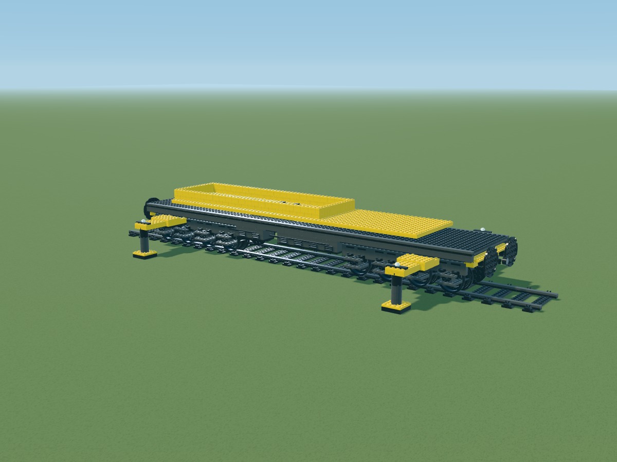
Positions belong to the digital model. Connections still require a physical prototype.
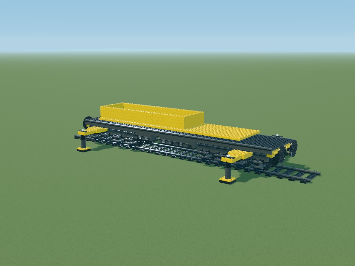
Positions belong to the digital model. Connections still require a physical prototype.
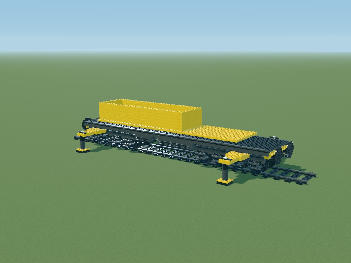
Positions belong to the digital model. Connections still require a physical prototype.
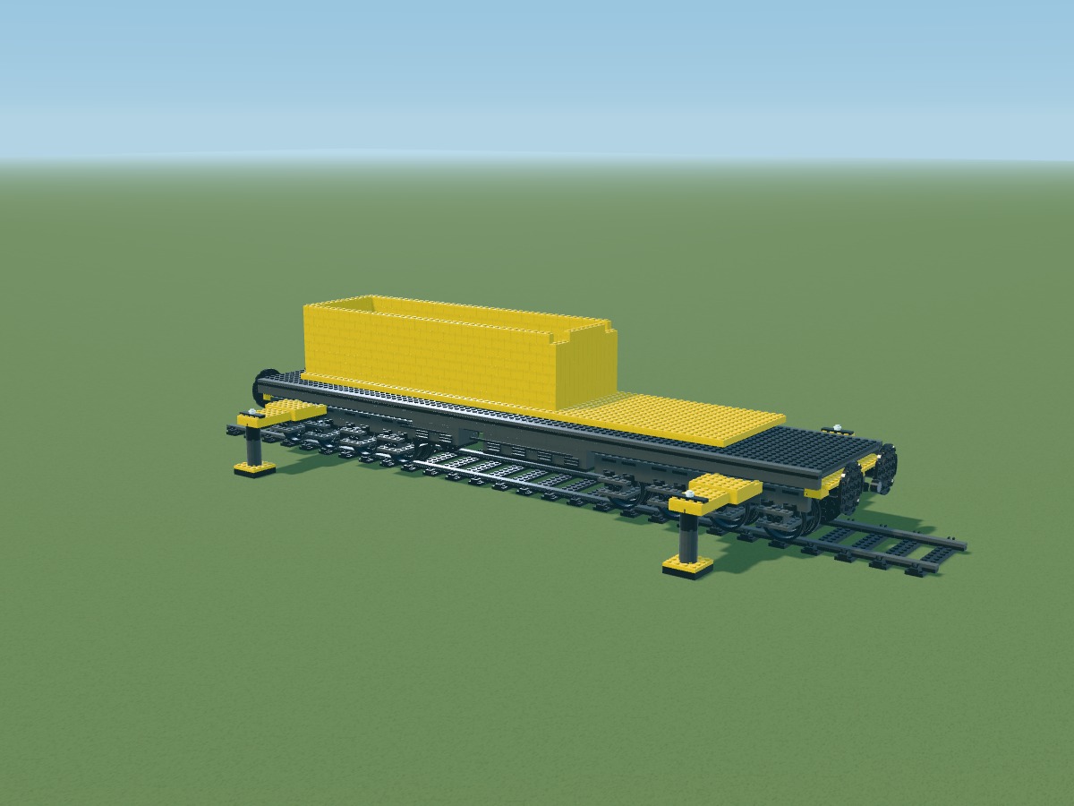
Positions belong to the digital model. Connections still require a physical prototype.
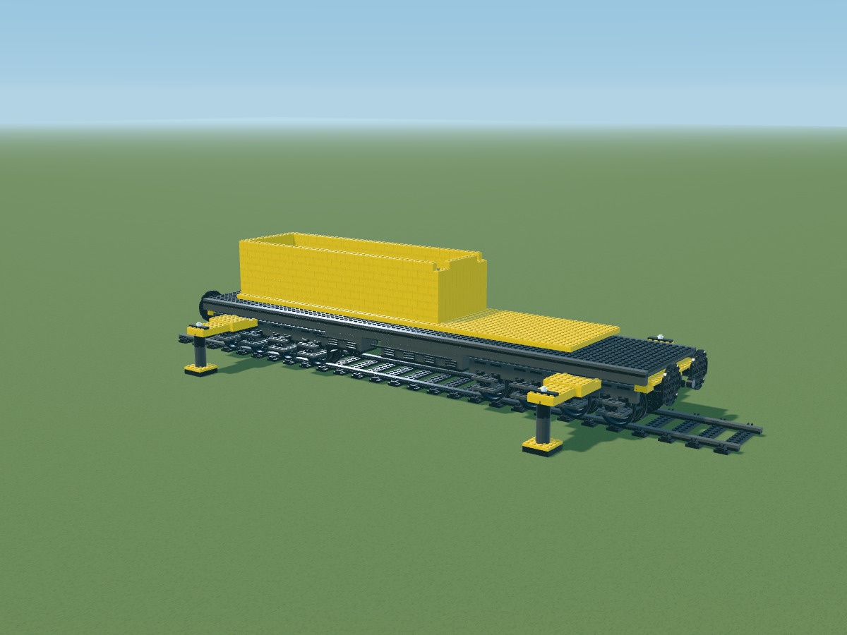
Positions belong to the digital model. Connections still require a physical prototype.
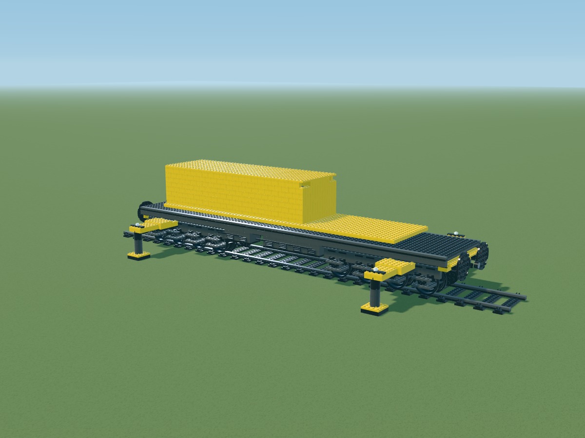
Positions belong to the digital model. Connections still require a physical prototype.
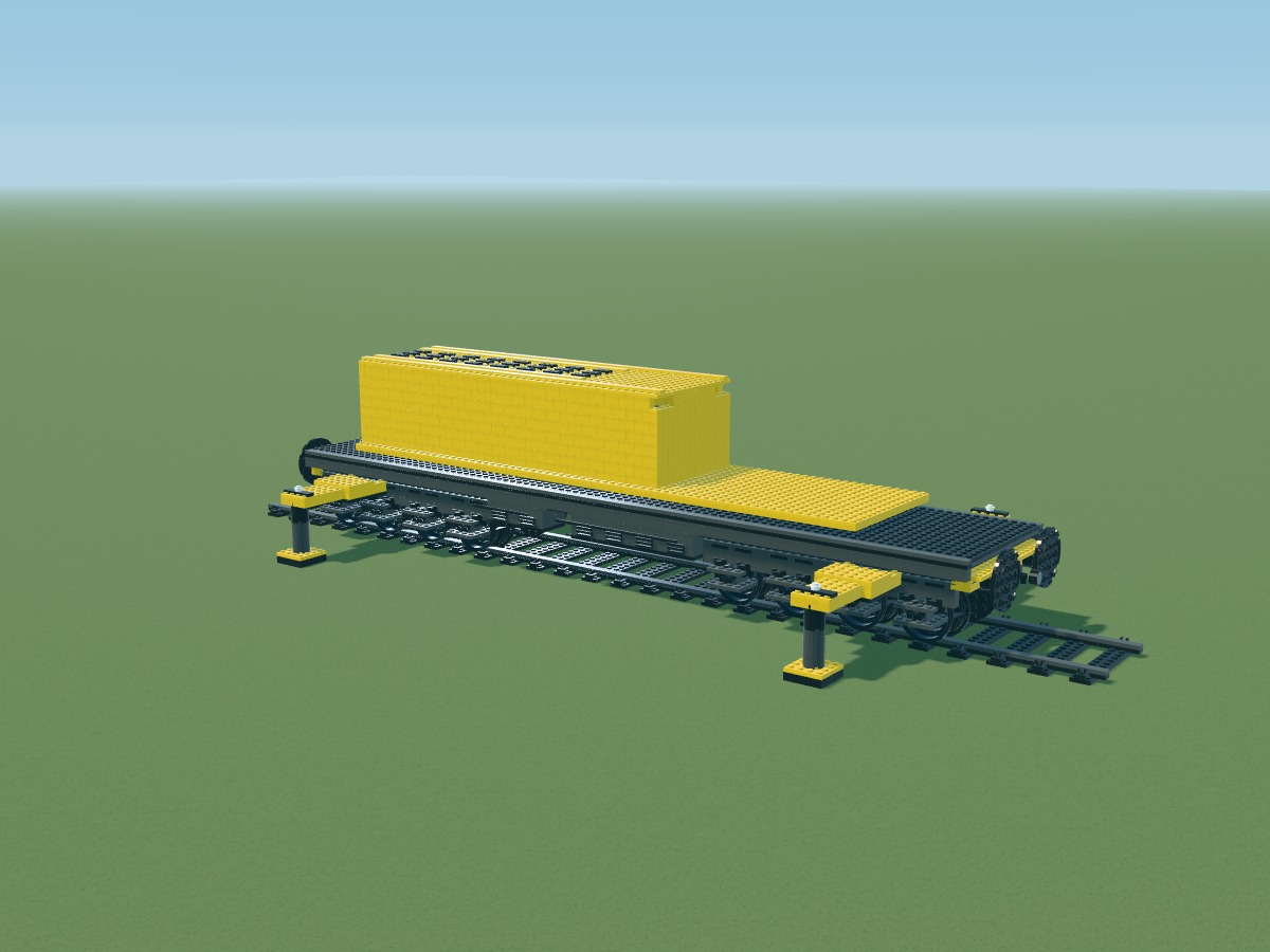
Positions belong to the digital model. Connections still require a physical prototype.
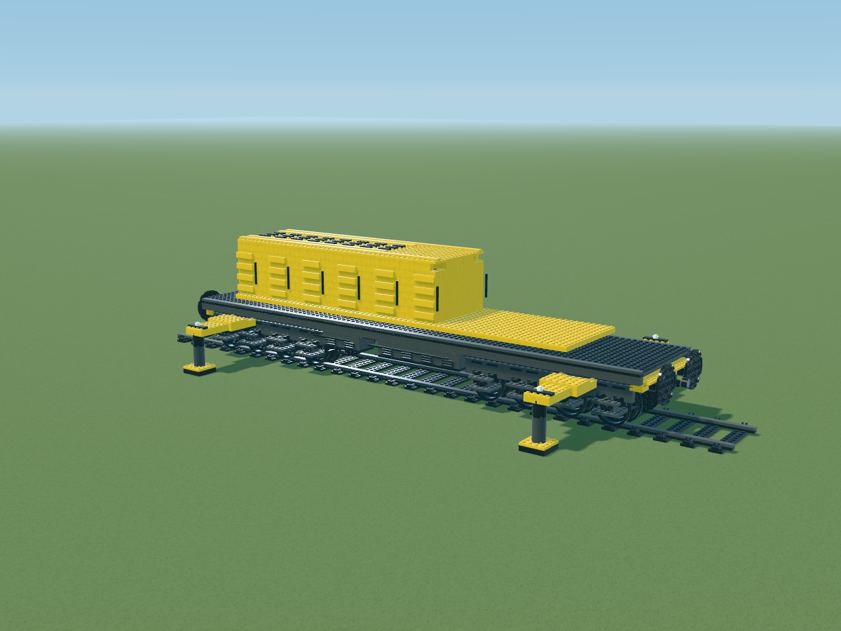
Positions belong to the digital model. Connections still require a physical prototype.
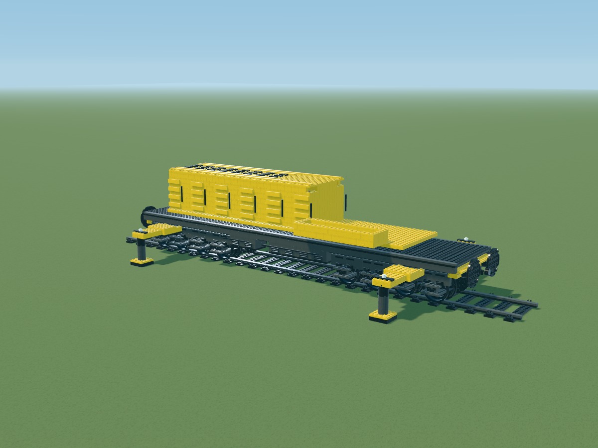
Positions belong to the digital model. Connections still require a physical prototype.
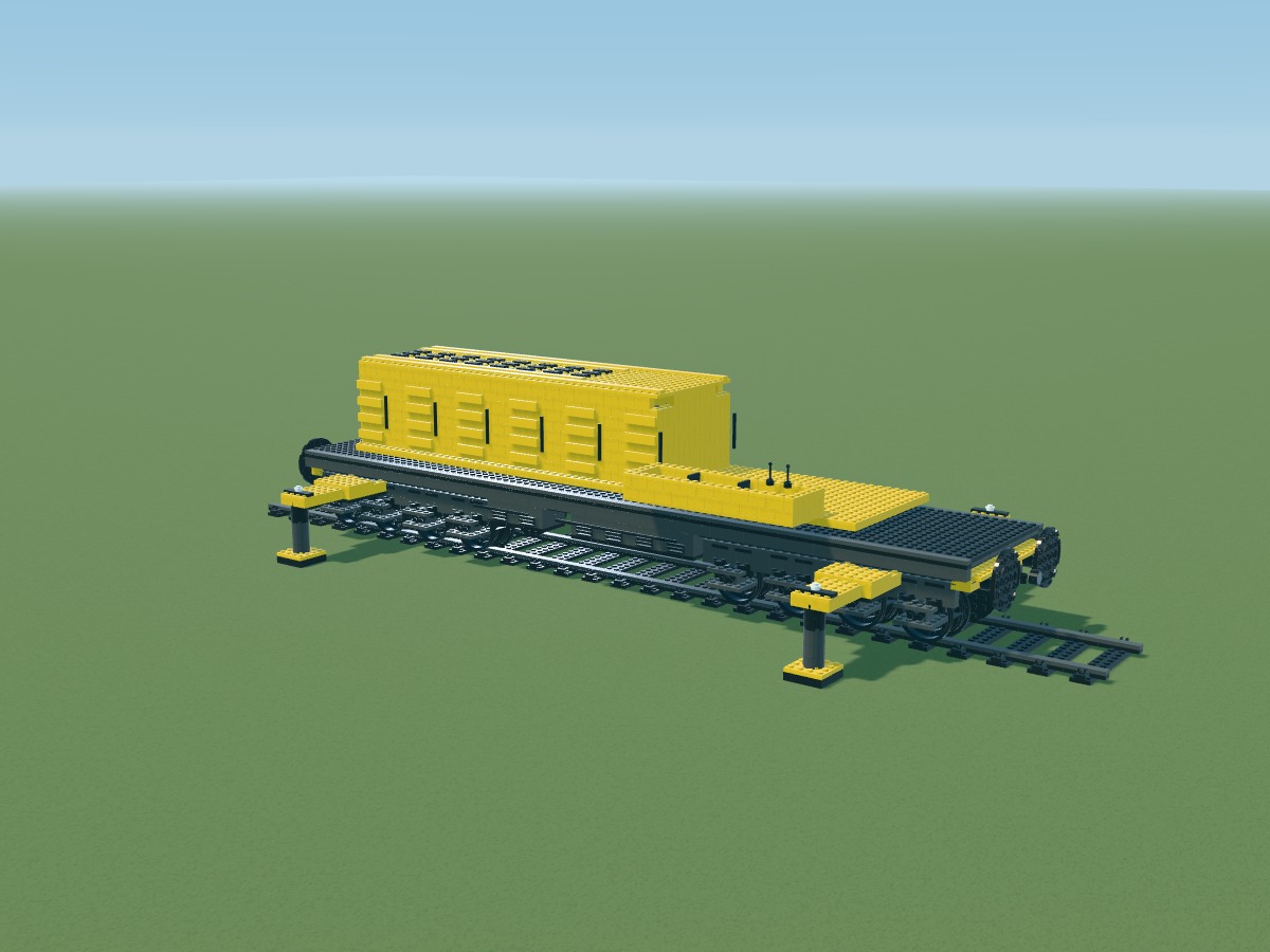
Positions belong to the digital model. Connections still require a physical prototype.
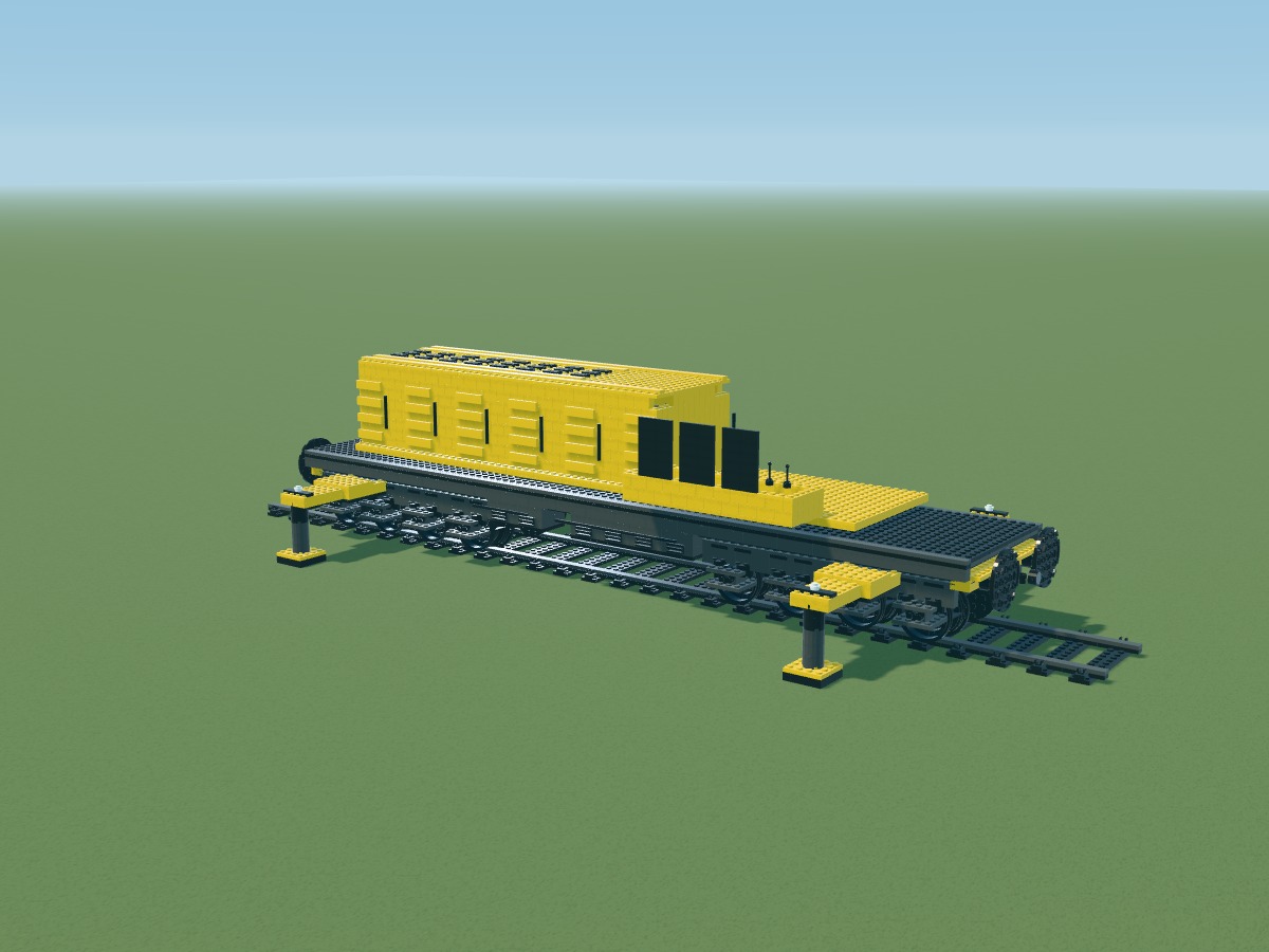
Black tiles represent the dark windows. These panels are opaque; their side connections remain to be tested.
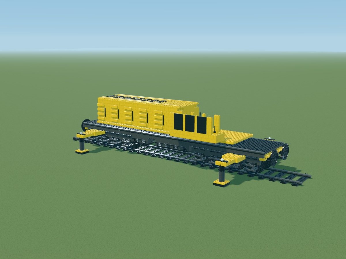
Positions belong to the digital model. Connections still require a physical prototype.
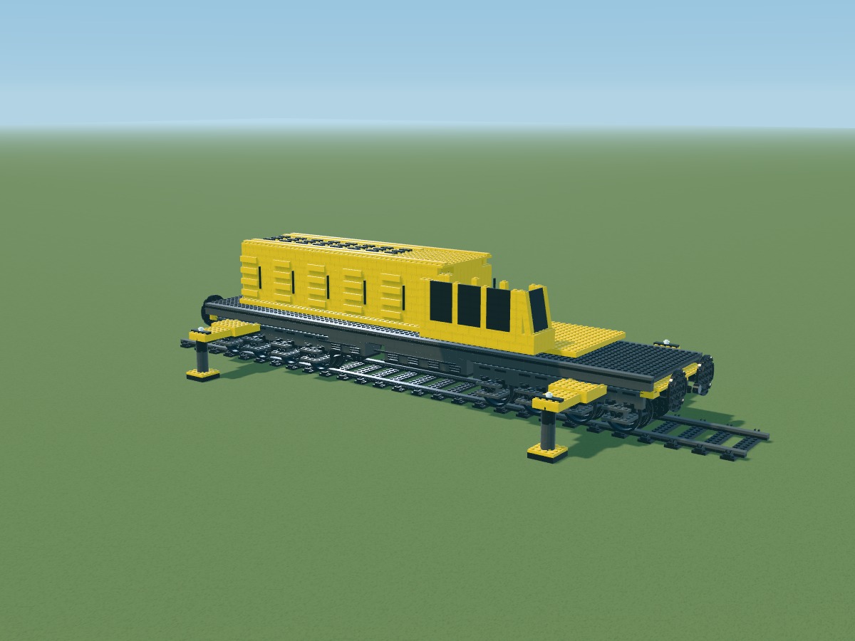
Positions belong to the digital model. Connections still require a physical prototype.
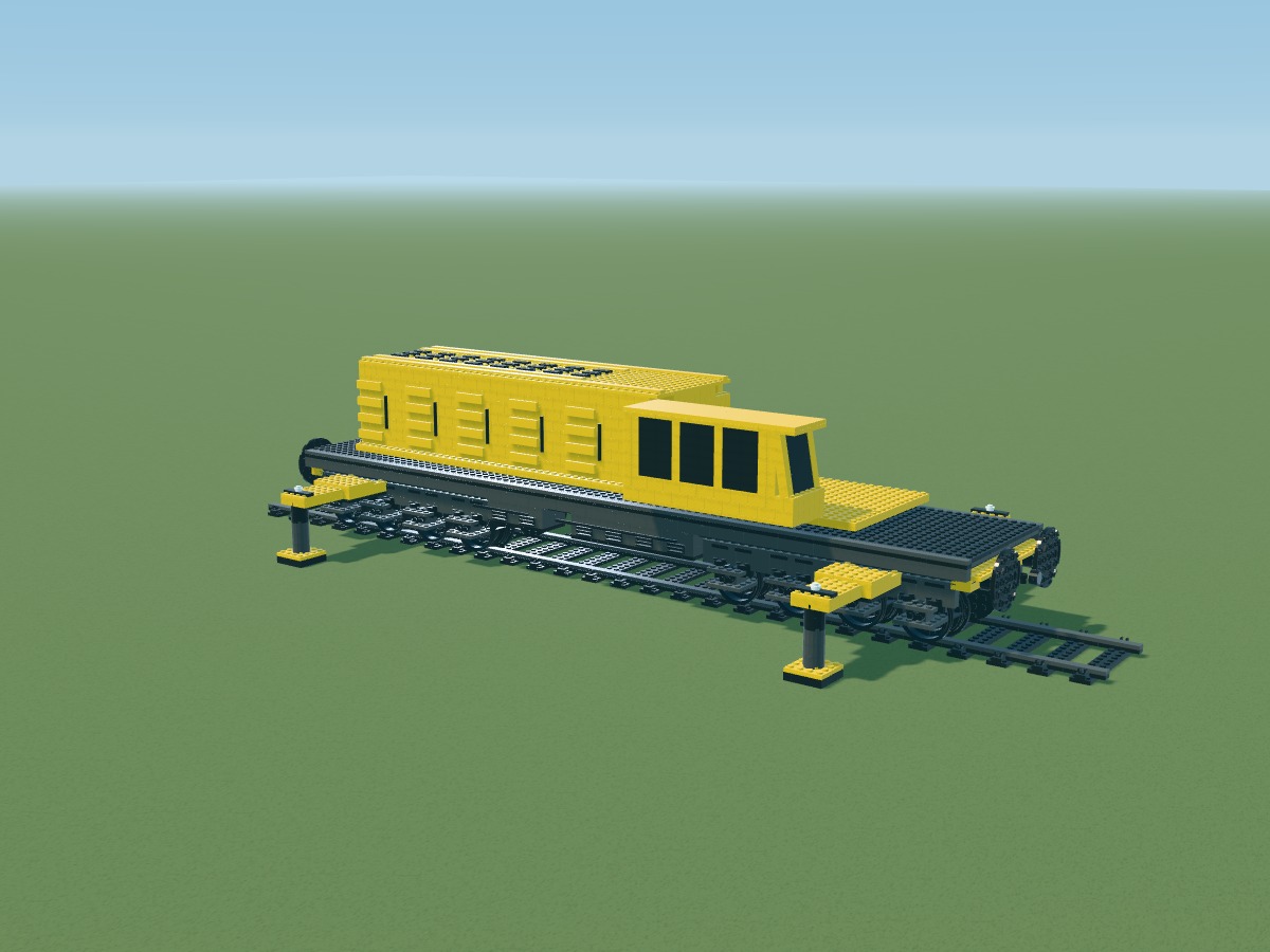
Positions belong to the digital model. Connections still require a physical prototype.
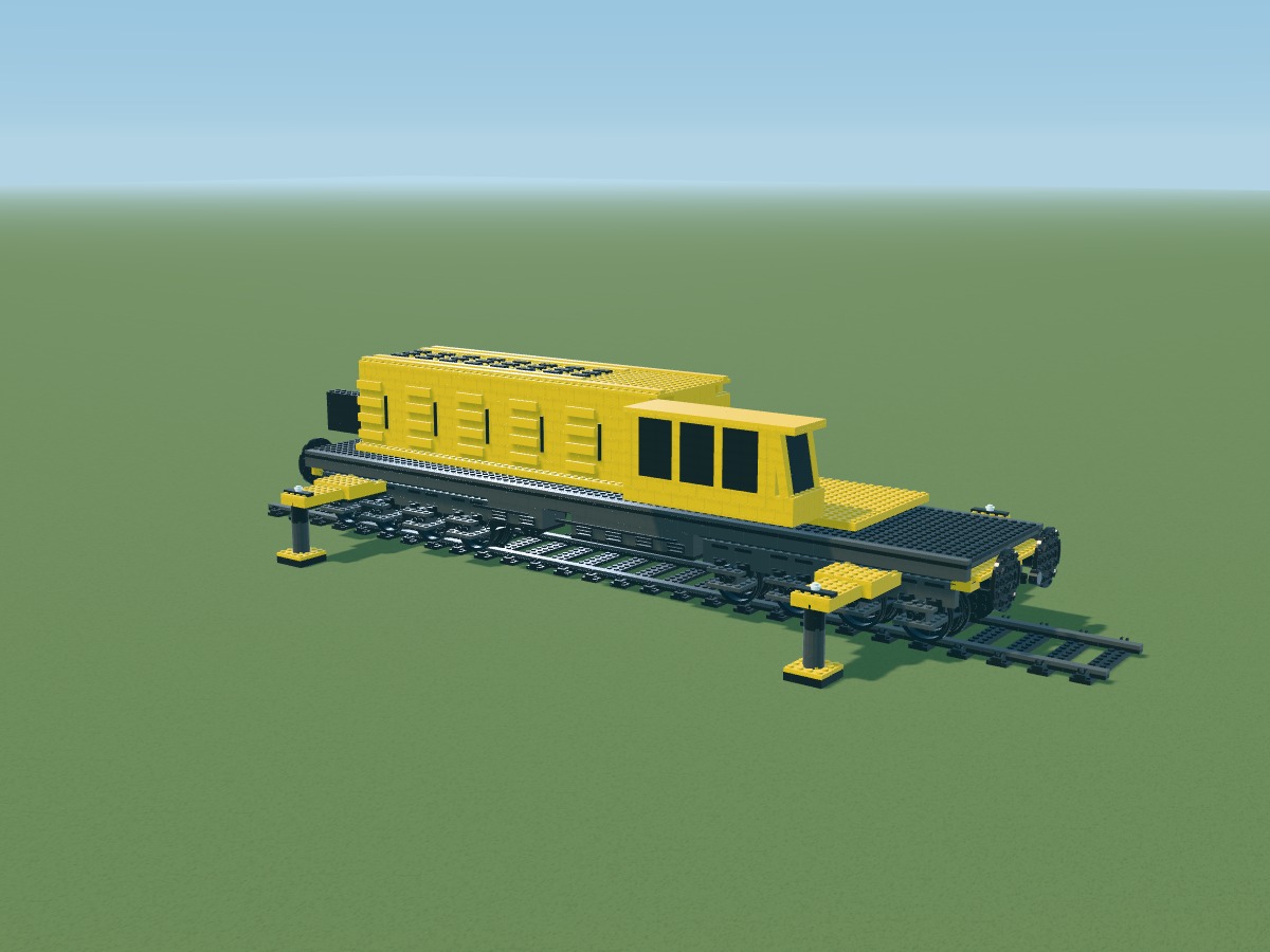
Positions belong to the digital model. Connections still require a physical prototype.
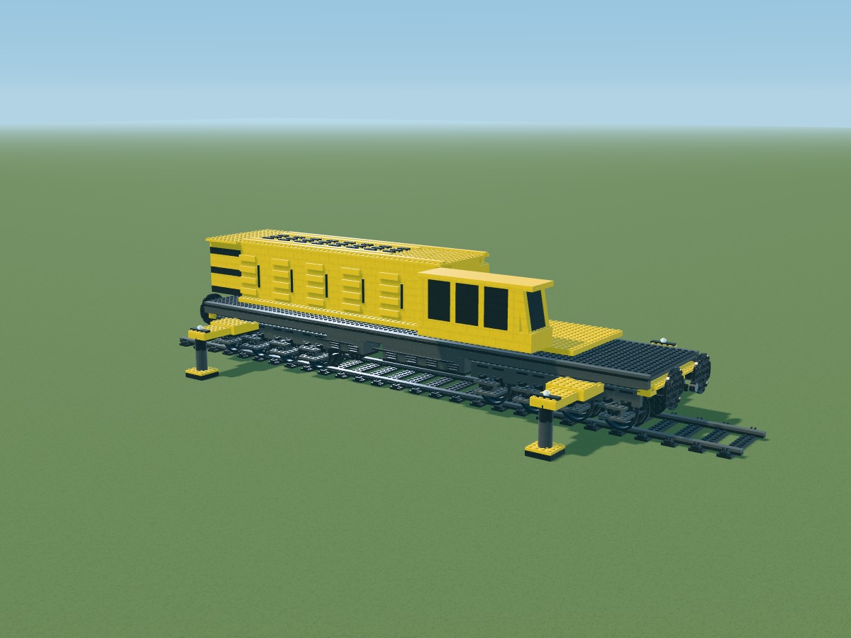
Positions belong to the digital model. Connections still require a physical prototype.
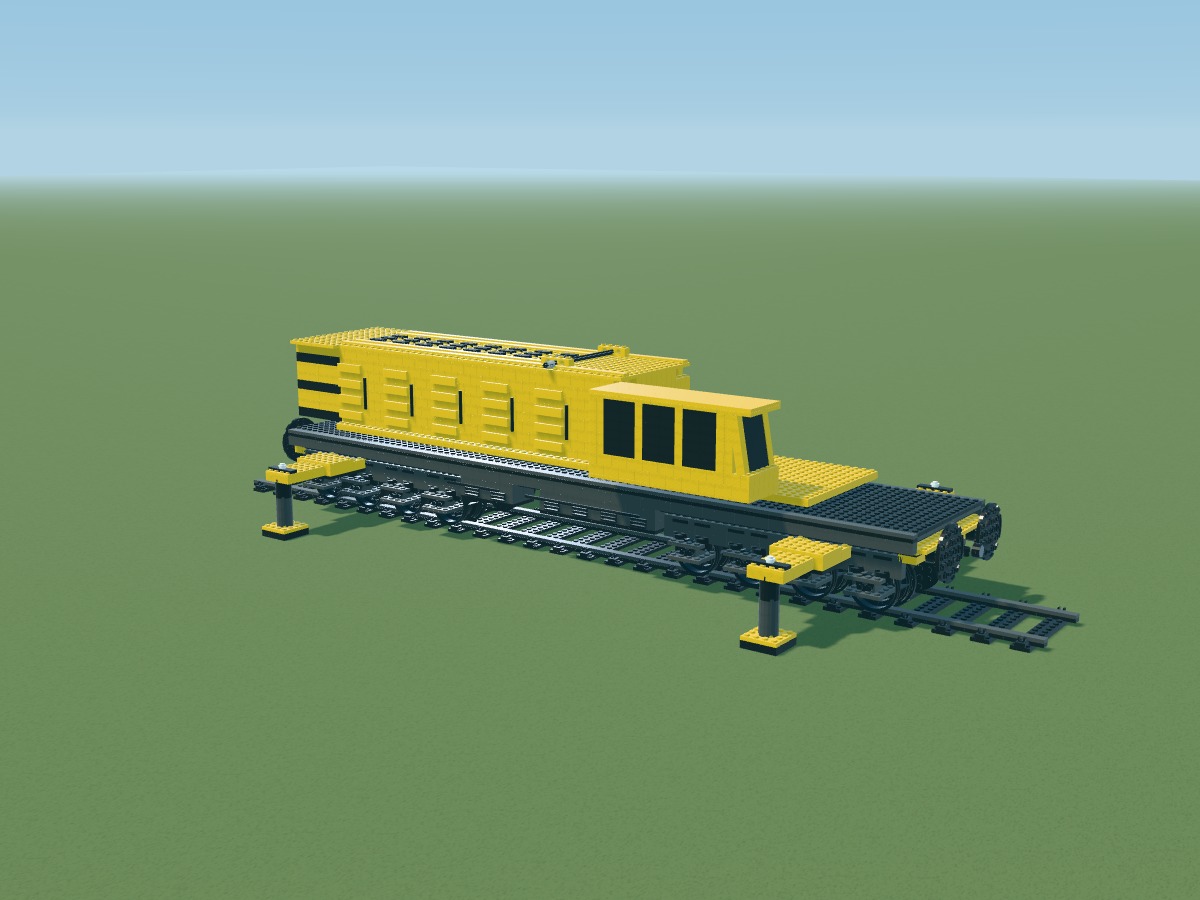
Positions belong to the digital model. Connections still require a physical prototype.
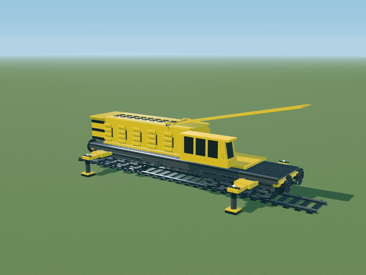
Positions belong to the digital model. Connections still require a physical prototype.
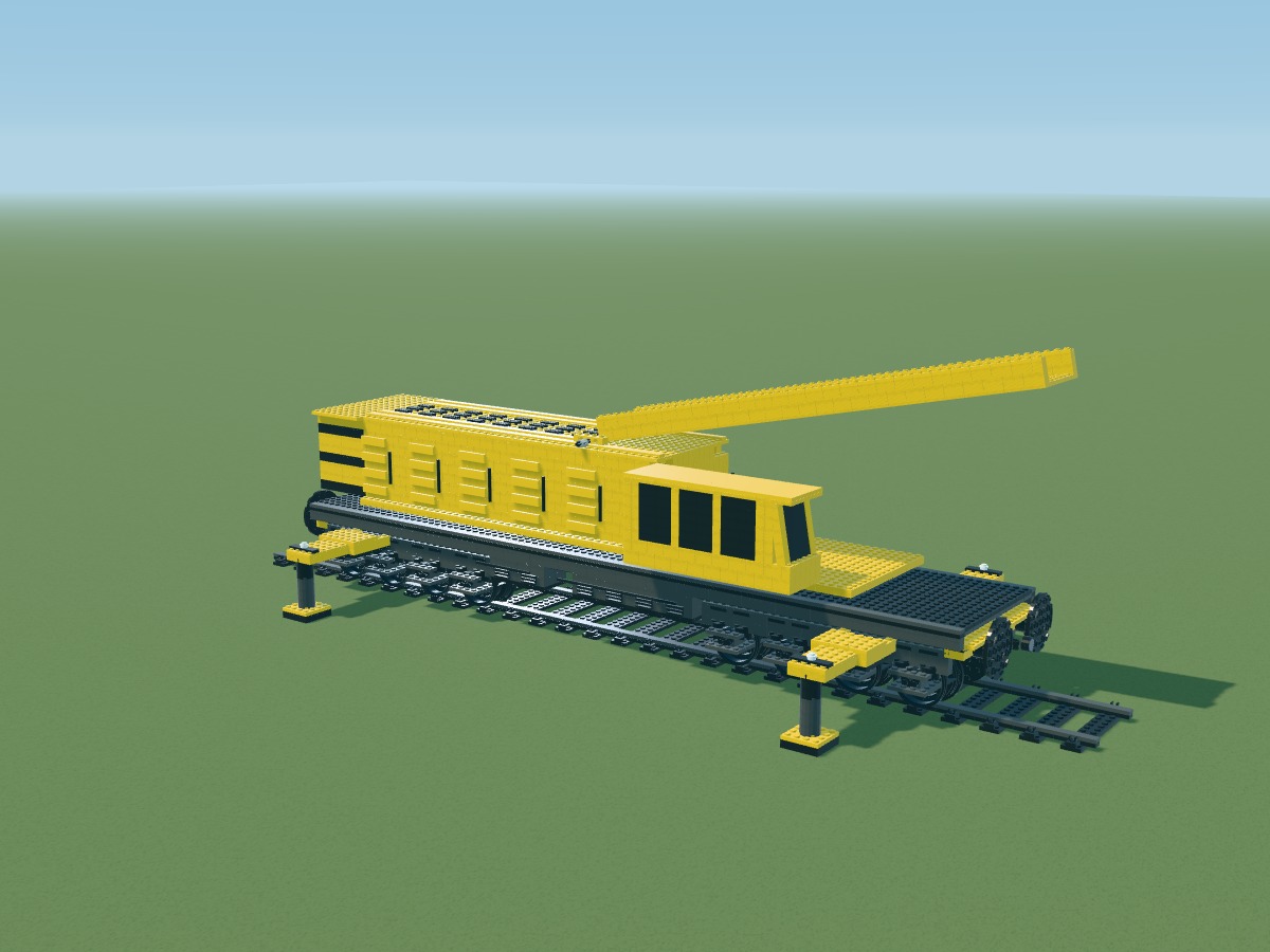
Positions belong to the digital model. Connections still require a physical prototype.
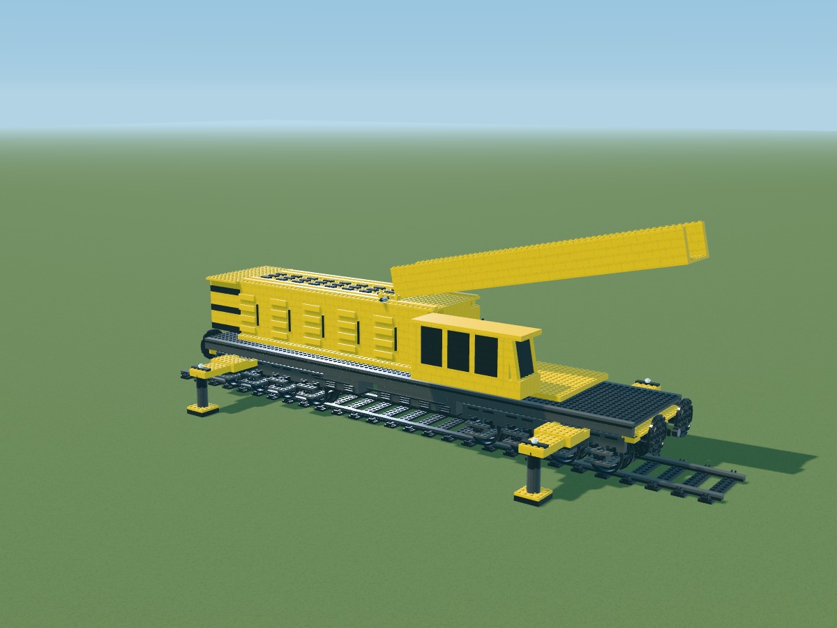
Positions belong to the digital model. Connections still require a physical prototype.
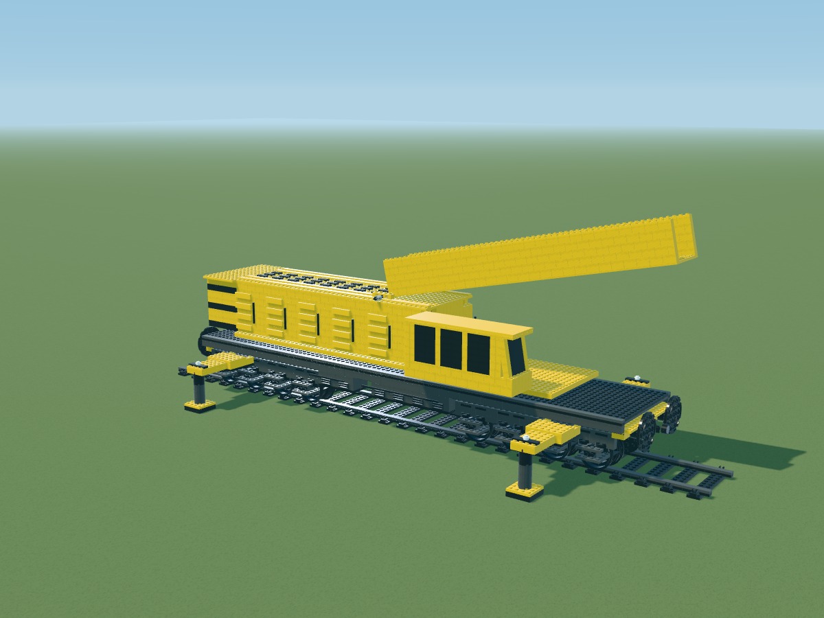
Positions belong to the digital model. Connections still require a physical prototype.
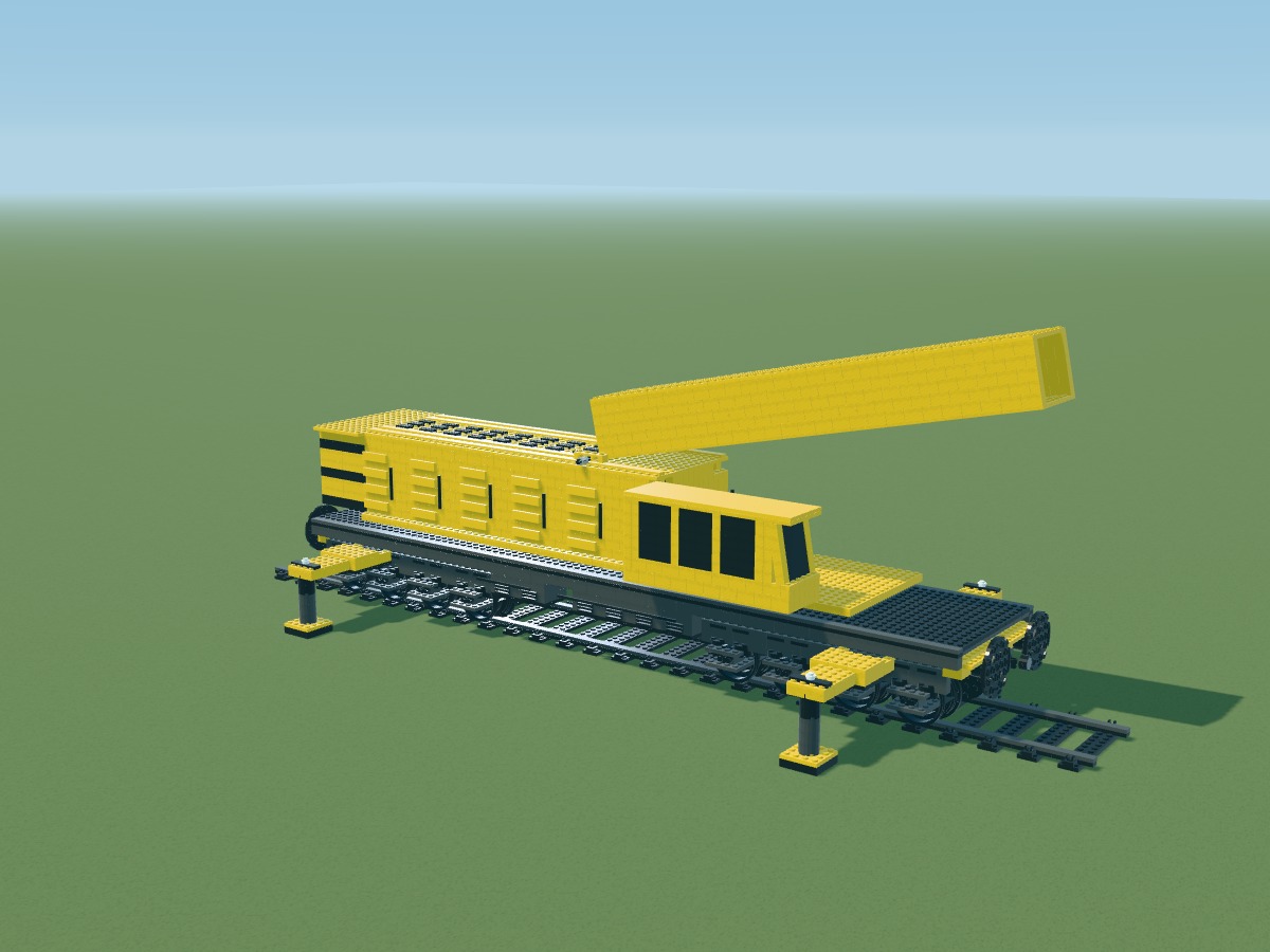
Positions belong to the digital model. Connections still require a physical prototype.
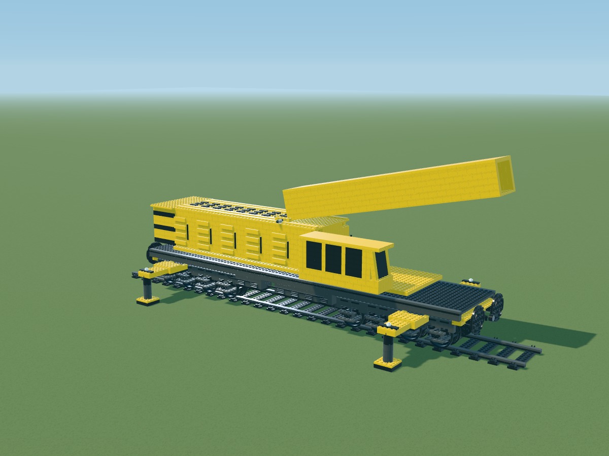
Positions belong to the digital model. Connections still require a physical prototype.
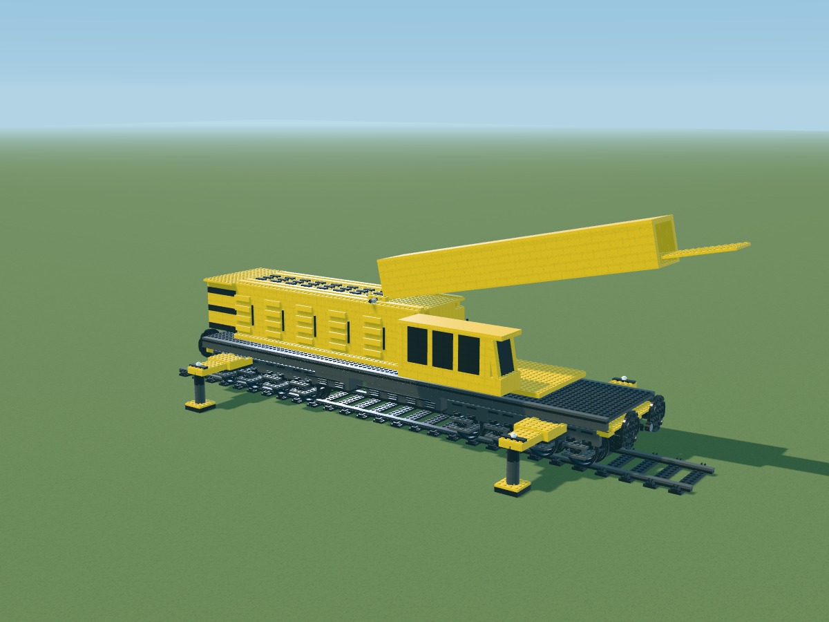
Positions belong to the digital model. Connections still require a physical prototype.
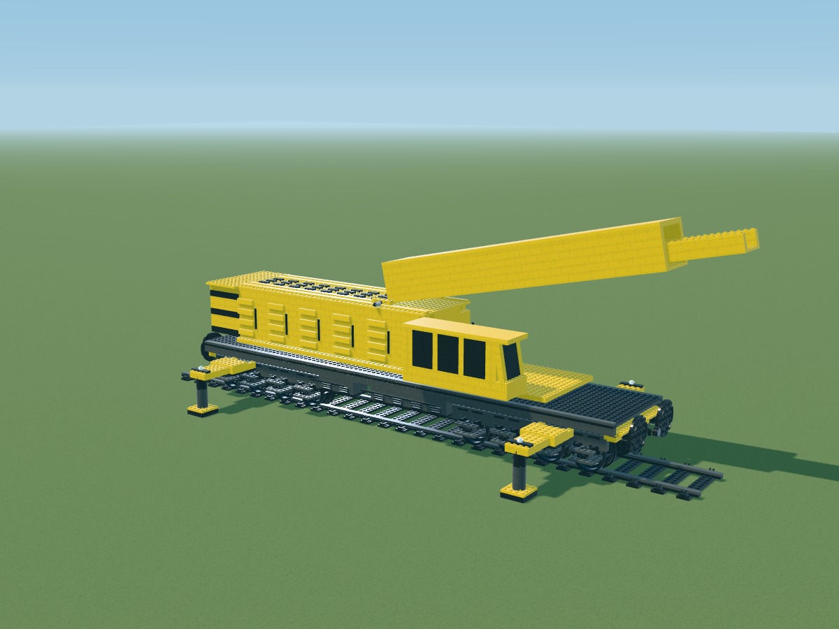
Positions belong to the digital model. Connections still require a physical prototype.
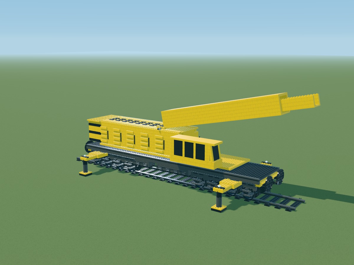
Positions belong to the digital model. Connections still require a physical prototype.
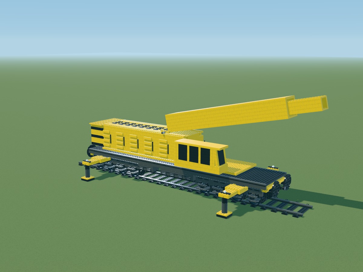
Positions belong to the digital model. Connections still require a physical prototype.
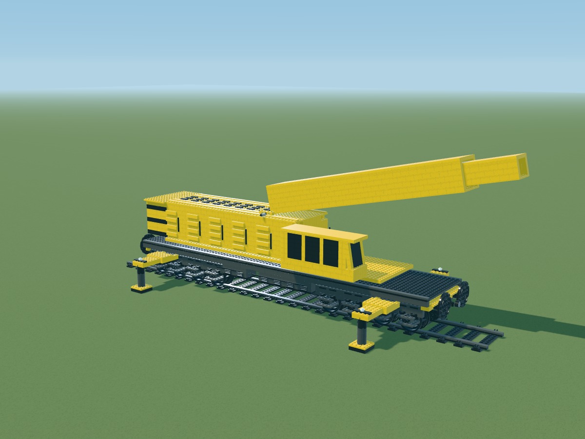
Positions belong to the digital model. Connections still require a physical prototype.
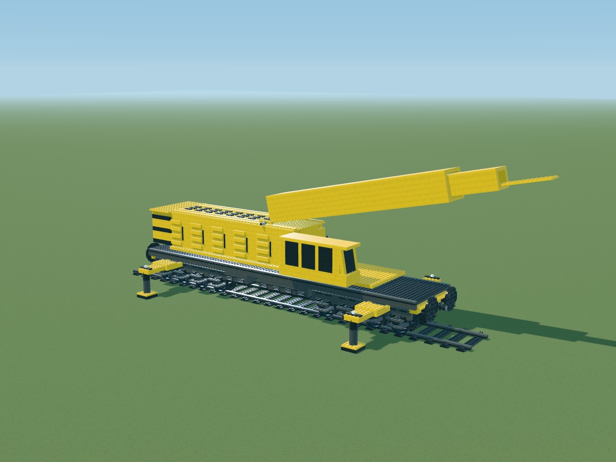
Positions belong to the digital model. Connections still require a physical prototype.
Positions belong to the digital model. Connections still require a physical prototype.
Positions belong to the digital model. Connections still require a physical prototype.
Positions belong to the digital model. Connections still require a physical prototype.
Positions belong to the digital model. Connections still require a physical prototype.
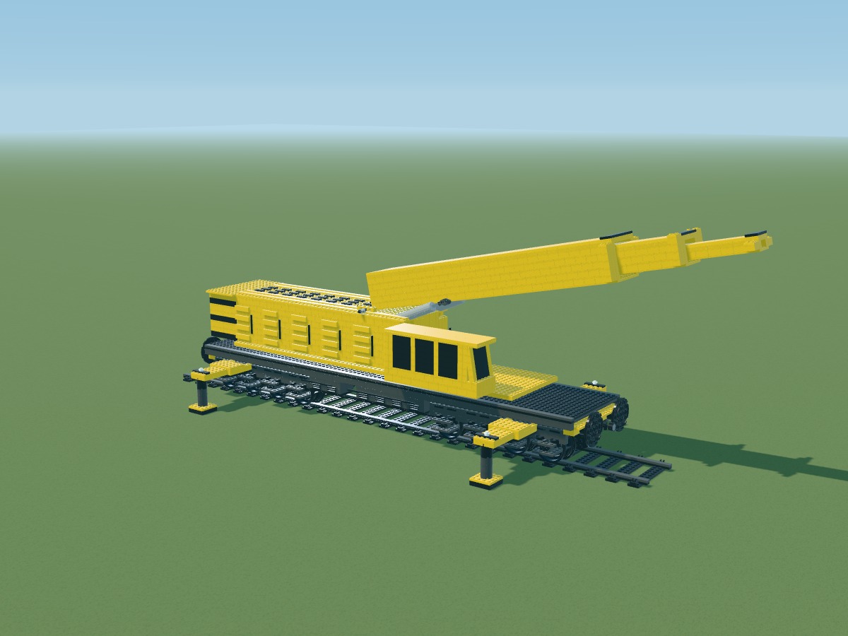
Positions belong to the digital model. Connections still require a physical prototype.
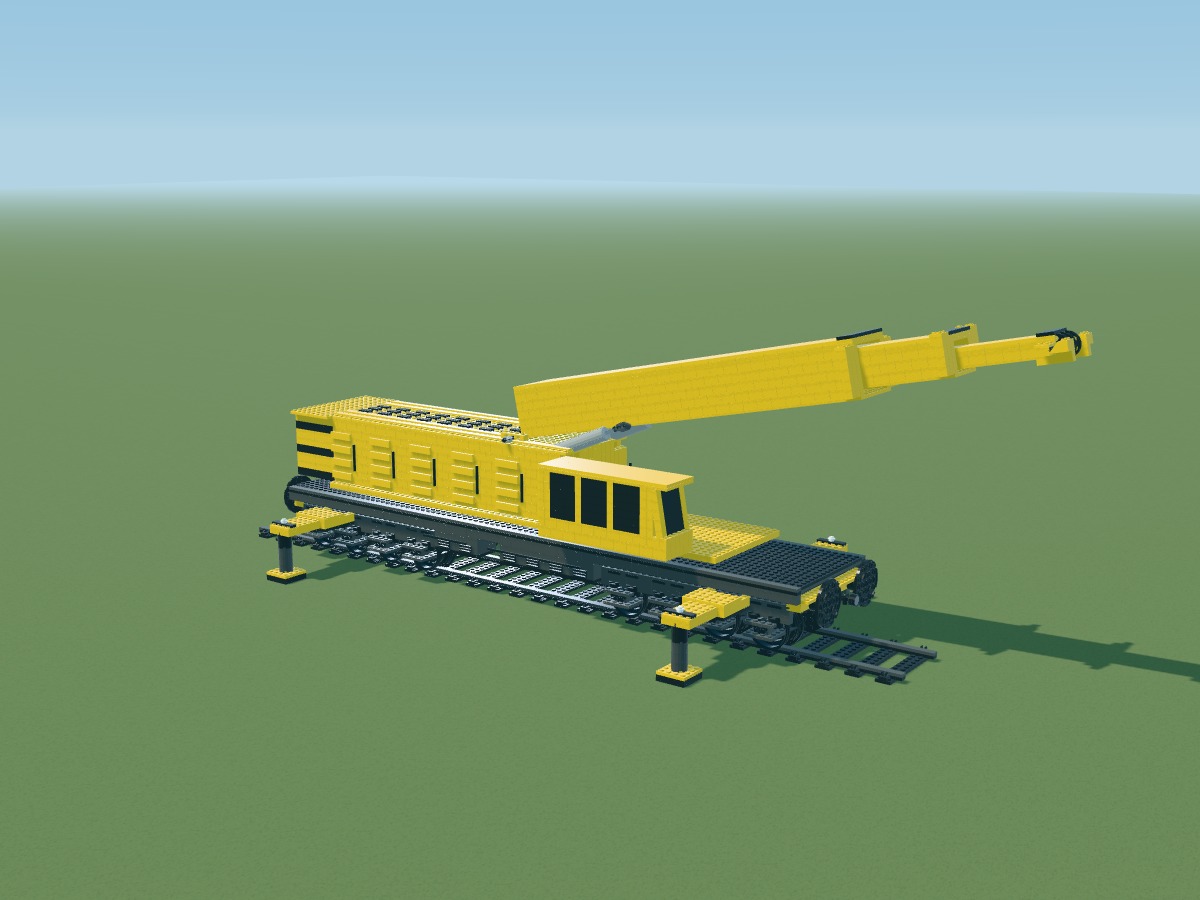
Positions belong to the digital model. Connections still require a physical prototype.
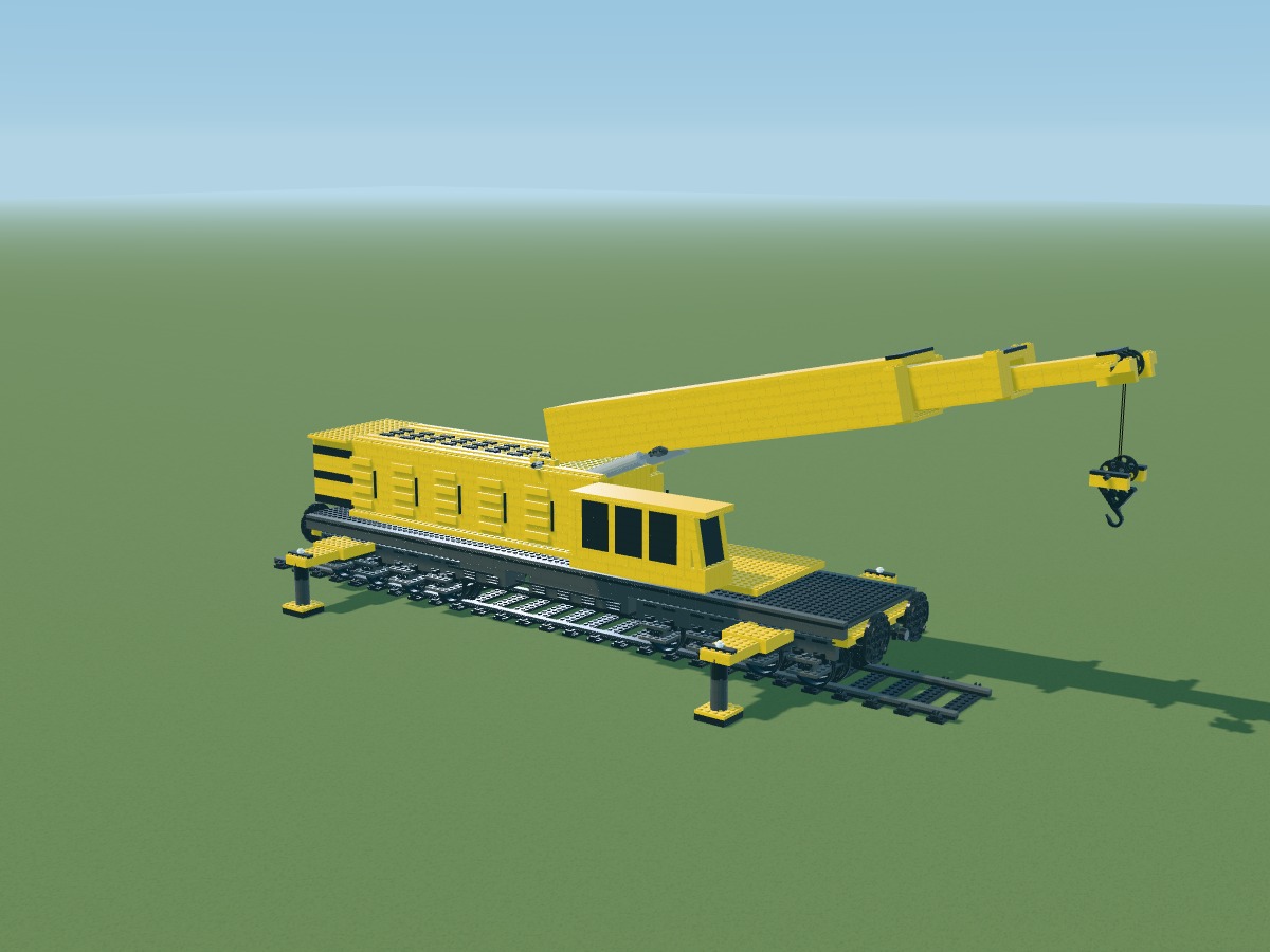
Positions belong to the digital model. Connections still require a physical prototype.
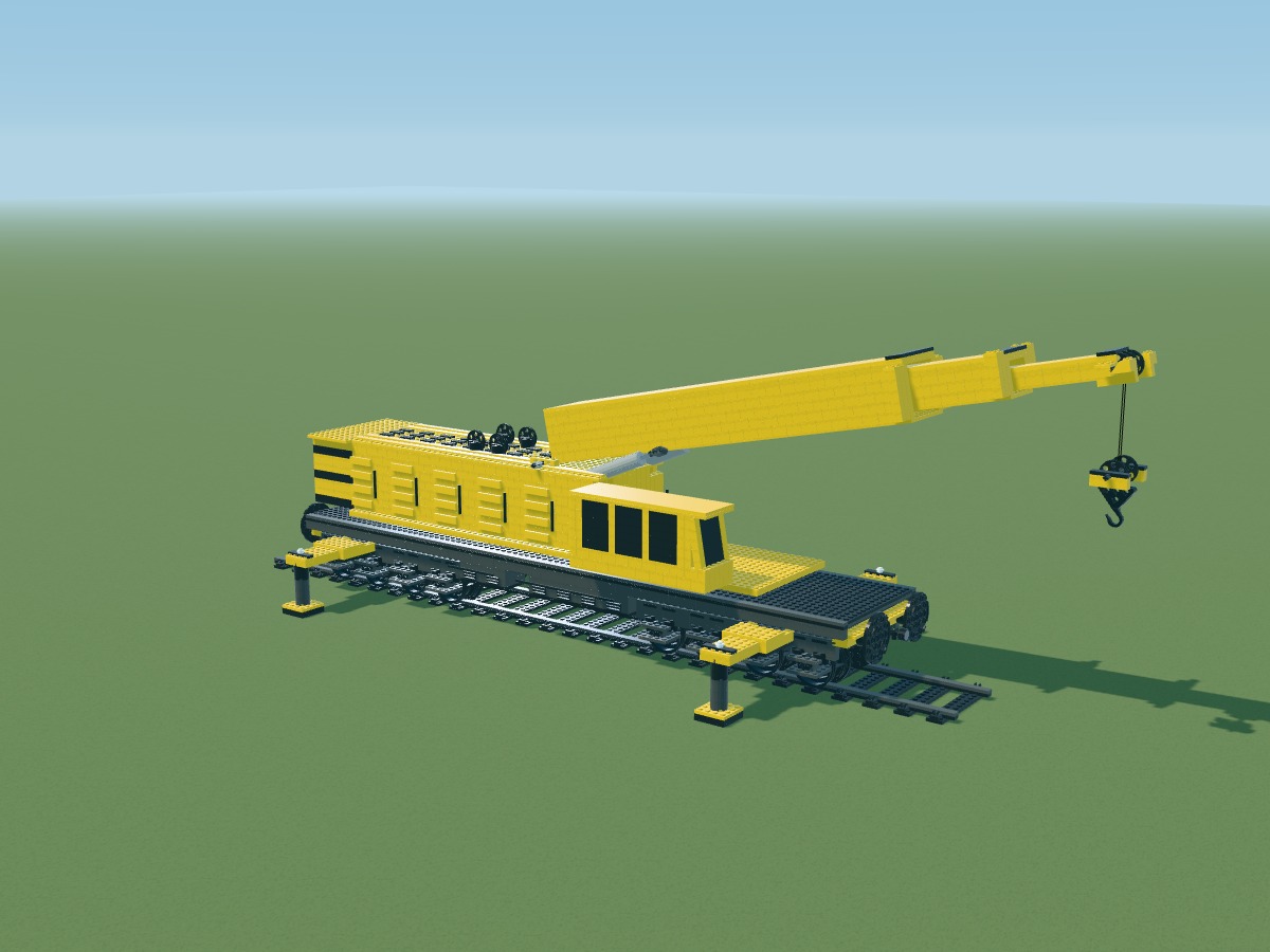
Positions belong to the digital model. Connections still require a physical prototype.
Positions belong to the digital model. Connections still require a physical prototype.
Positions belong to the digital model. Connections still require a physical prototype.
Positions belong to the digital model. Connections still require a physical prototype.
Positions belong to the digital model. Connections still require a physical prototype.
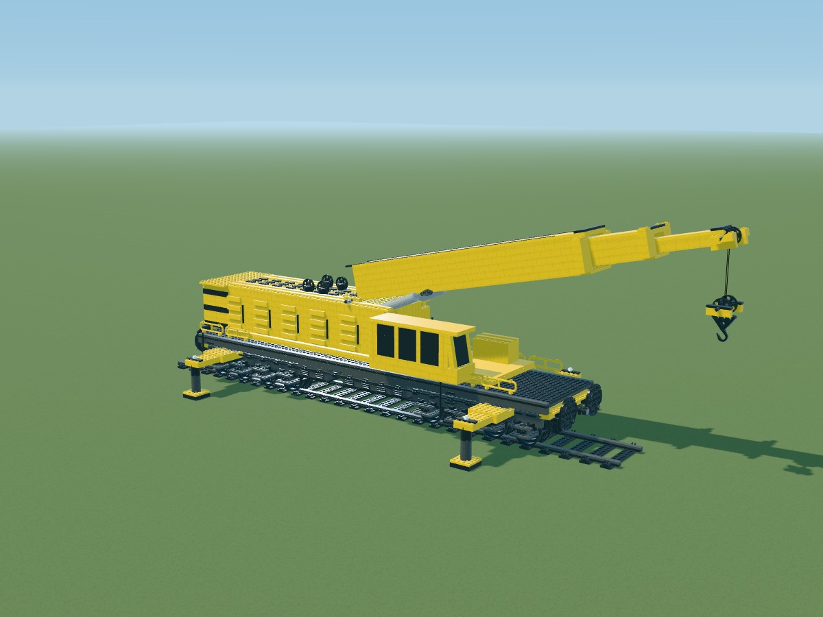
Positions belong to the digital model. Connections still require a physical prototype.
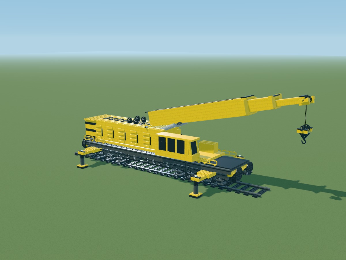
Positions belong to the digital model. Connections still require a physical prototype.
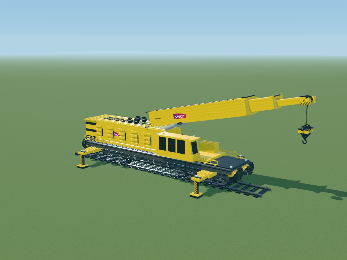
Positions belong to the digital model. Connections still require a physical prototype.
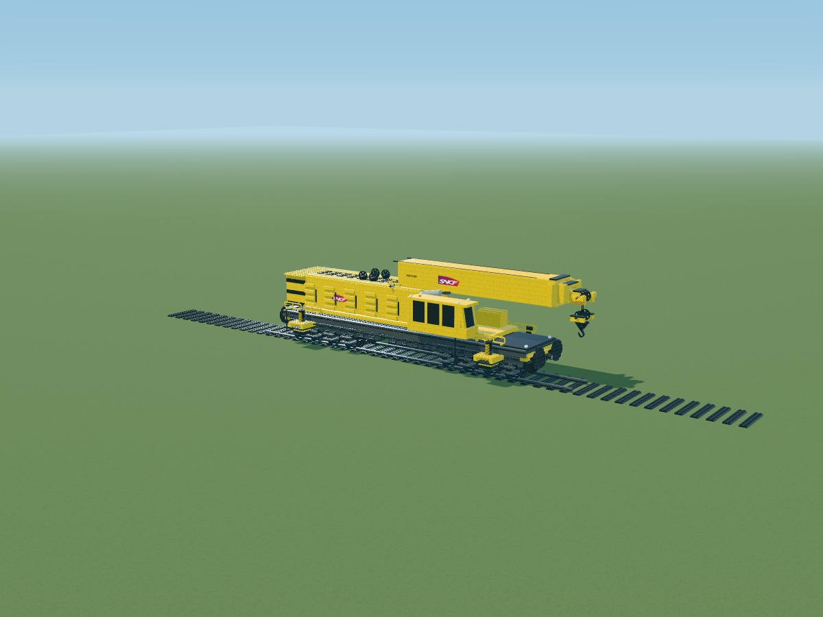
Extend both ends of the existing track to 104 studs from the centre. Sleepers use actual-size LEGO plates.
Two rows of plates support the running surfaces, aligned with the central track.
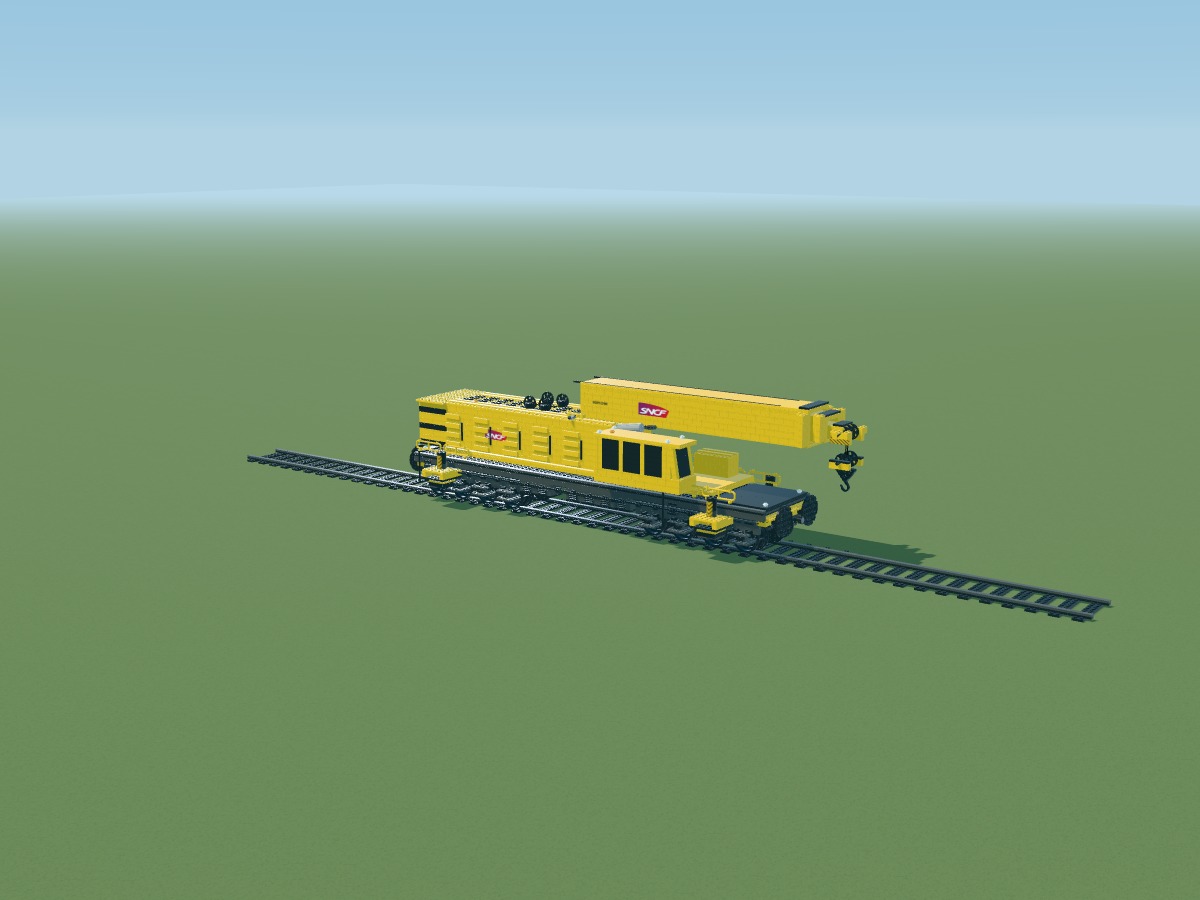
Cover the rail beds with tiles. This display track is not a tested railway system.
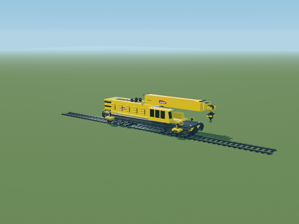
Add clips on both sides of the rails, continuing the central track pattern.
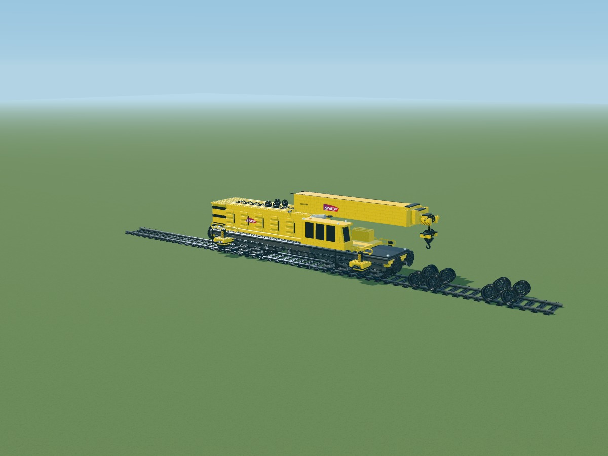
Each wagon has two two-axle bogies. Wheels 56908 retain their 43.2 mm diameter; 16L axles run across the wagon.
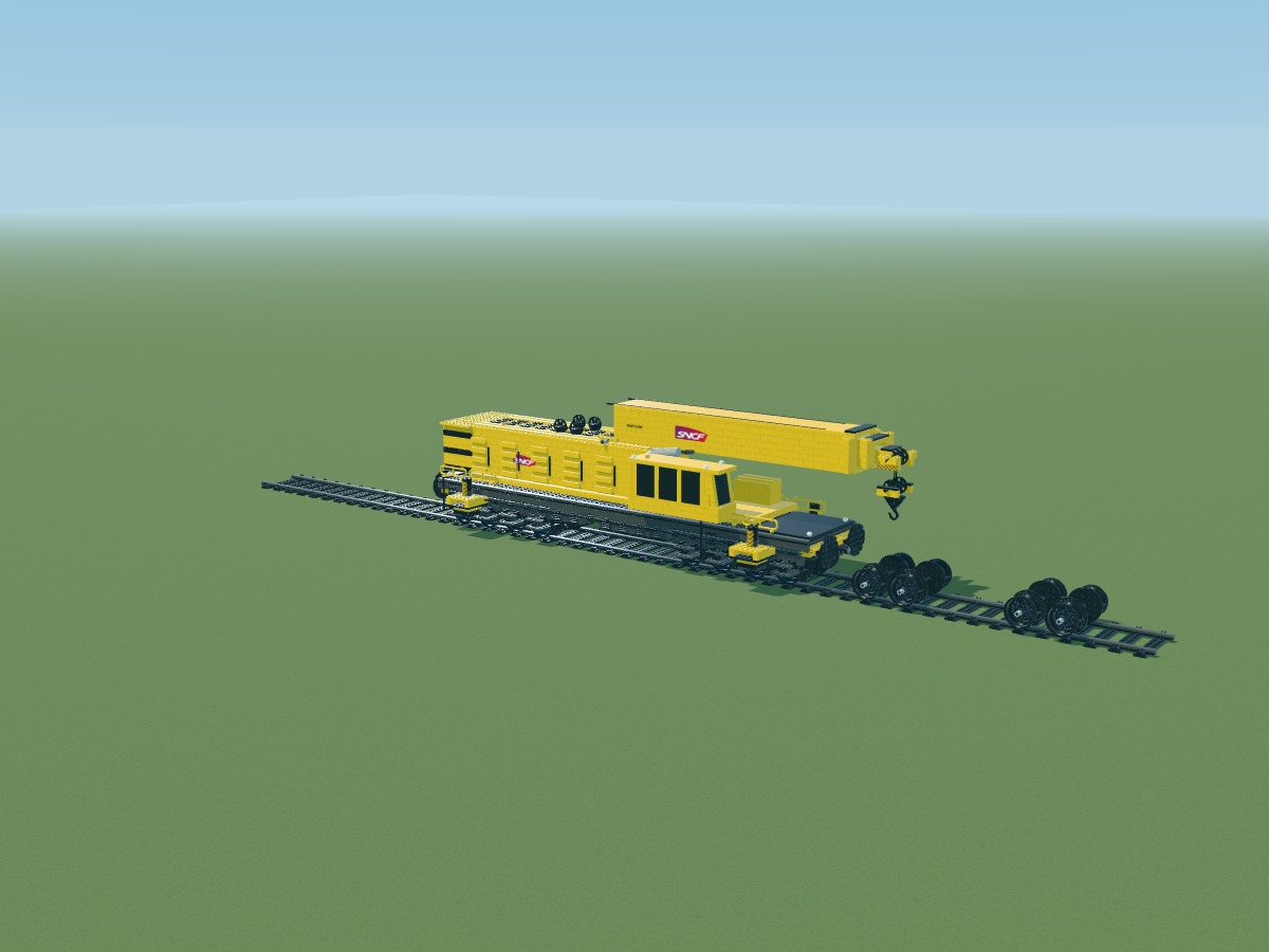
Round plates 11213 suggest railway wheel flanges. Their attachment to the wheels and rail guidance still require a physical prototype.
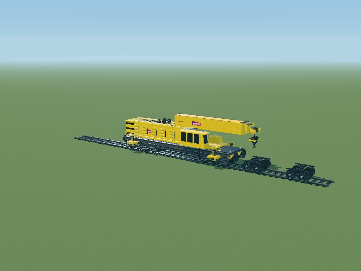
Build the frames above the wheels. Bogie beams and cross-members remain distinct from the main deck.
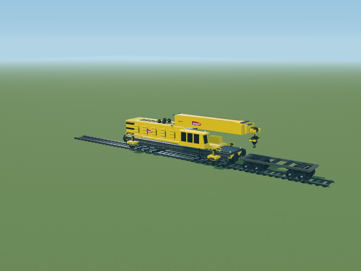
Place the 44-stud side beams and cross-members. They support the 14-stud-wide deck.
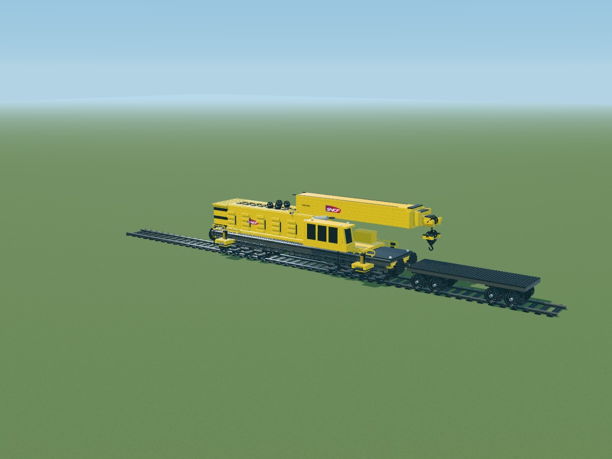
Cover the deck with 2 × 4 plates, without enlarging any part. The surface measures 44 × 14 studs.
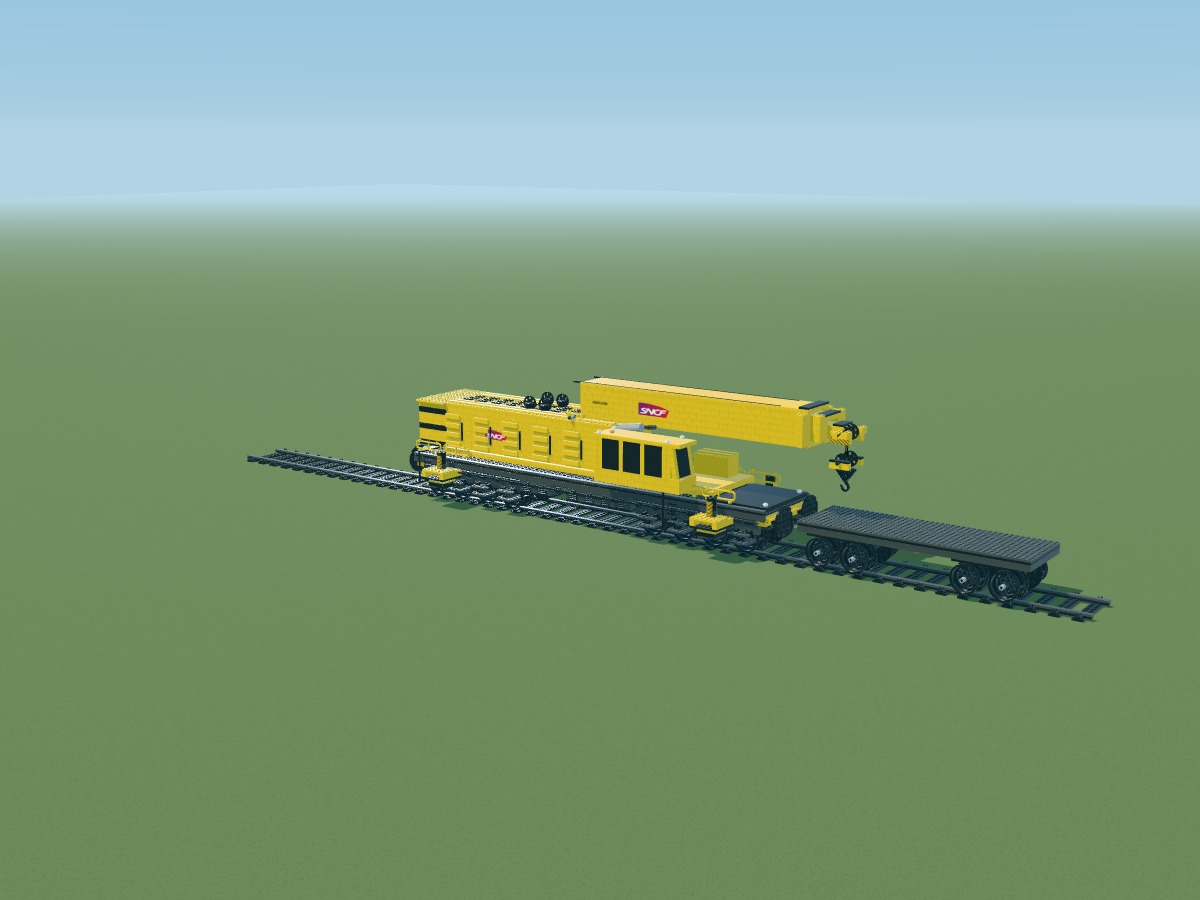
Turn the plates to stagger deck joints. The final strip completes the exact 14-stud width.
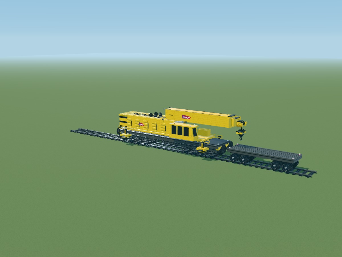
Add smooth deck edges and small end lights. Colors are named in the inventory.
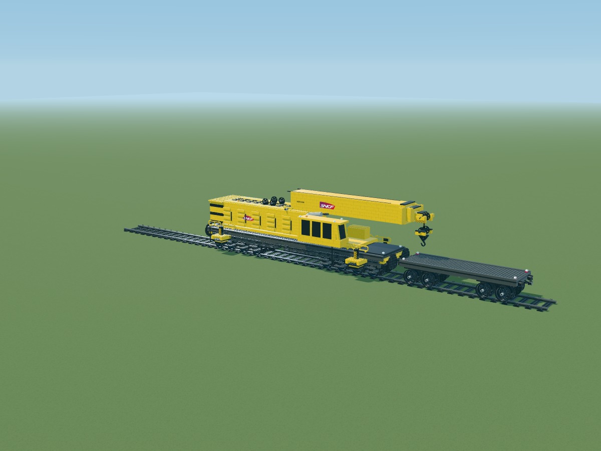
Fit brick-built buffers and couplers at both ends. Coupling the full convoy requires physical validation.
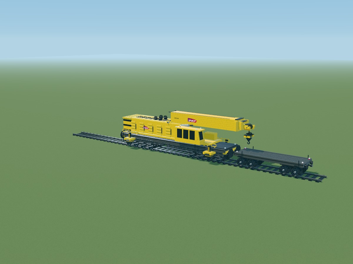
Add small access steps and handholds near the deck ends.
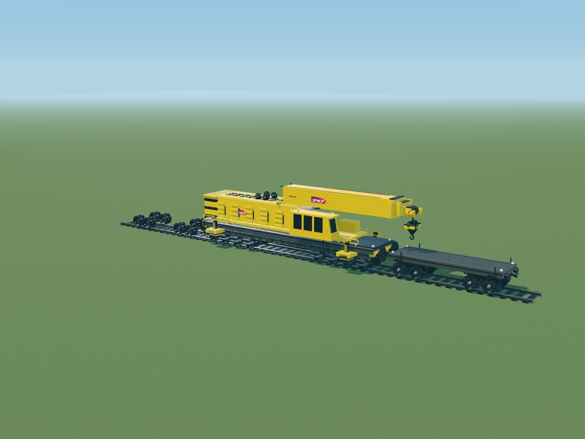
Each wagon has two two-axle bogies. Wheels 56908 retain their 43.2 mm diameter; 16L axles run across the wagon.
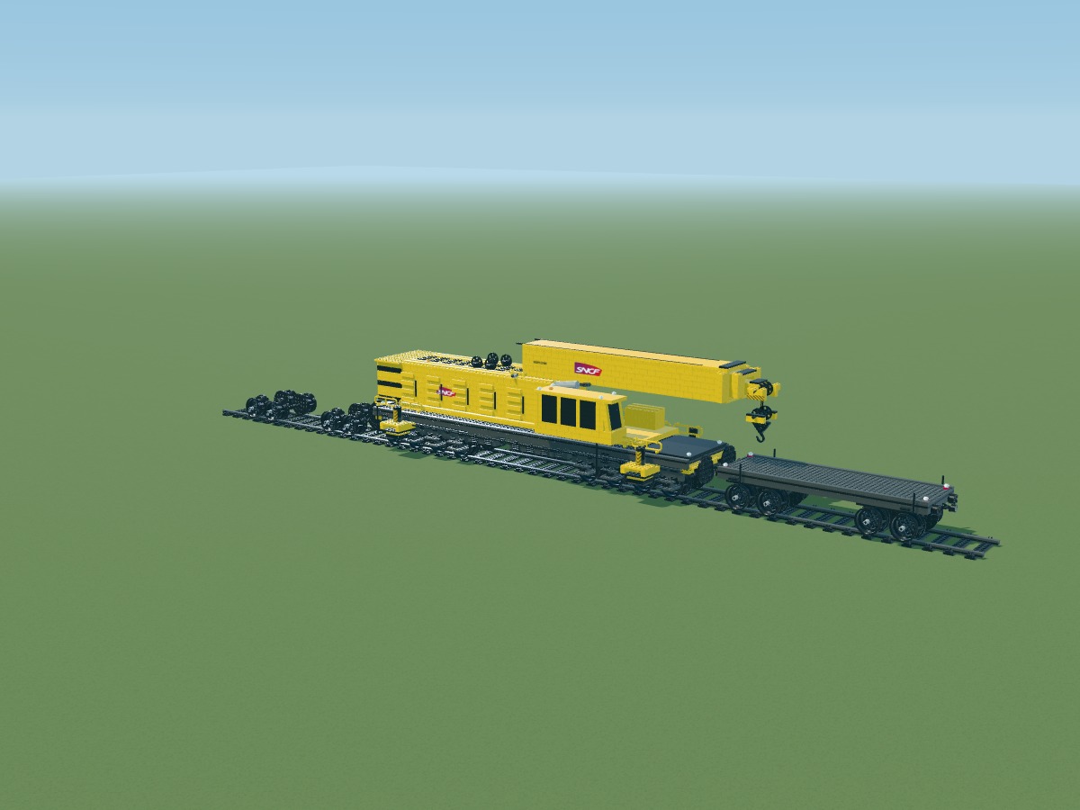
Round plates 11213 suggest railway wheel flanges. Their attachment to the wheels and rail guidance still require a physical prototype.
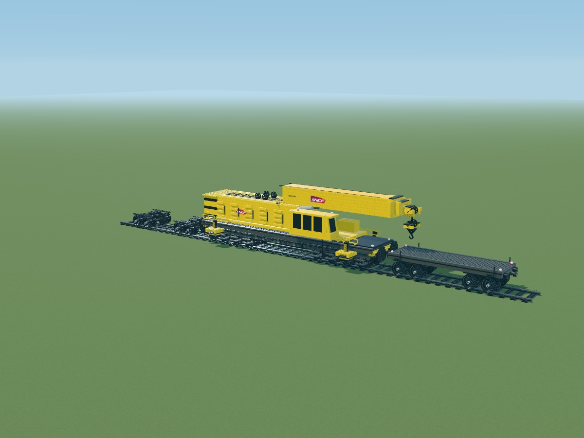
Build the frames above the wheels. Bogie beams and cross-members remain distinct from the main deck.
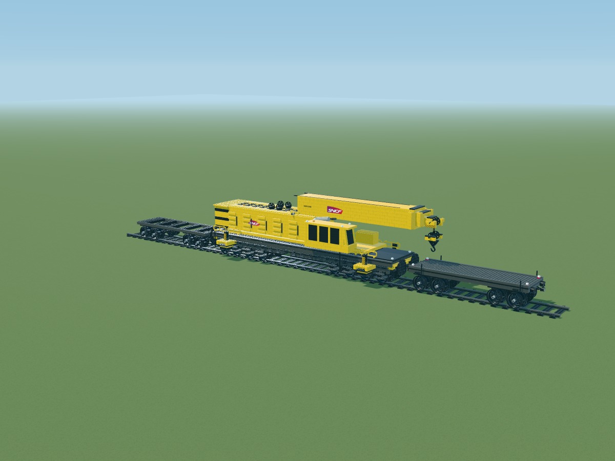
Place the 44-stud side beams and cross-members. They support the 14-stud-wide deck.
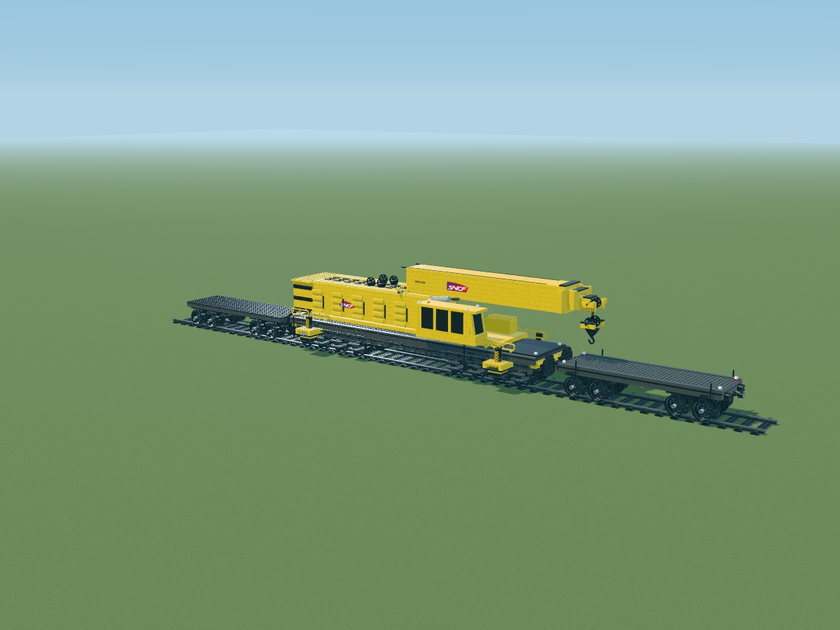
Cover the deck with 2 × 4 plates, without enlarging any part. The surface measures 44 × 14 studs.
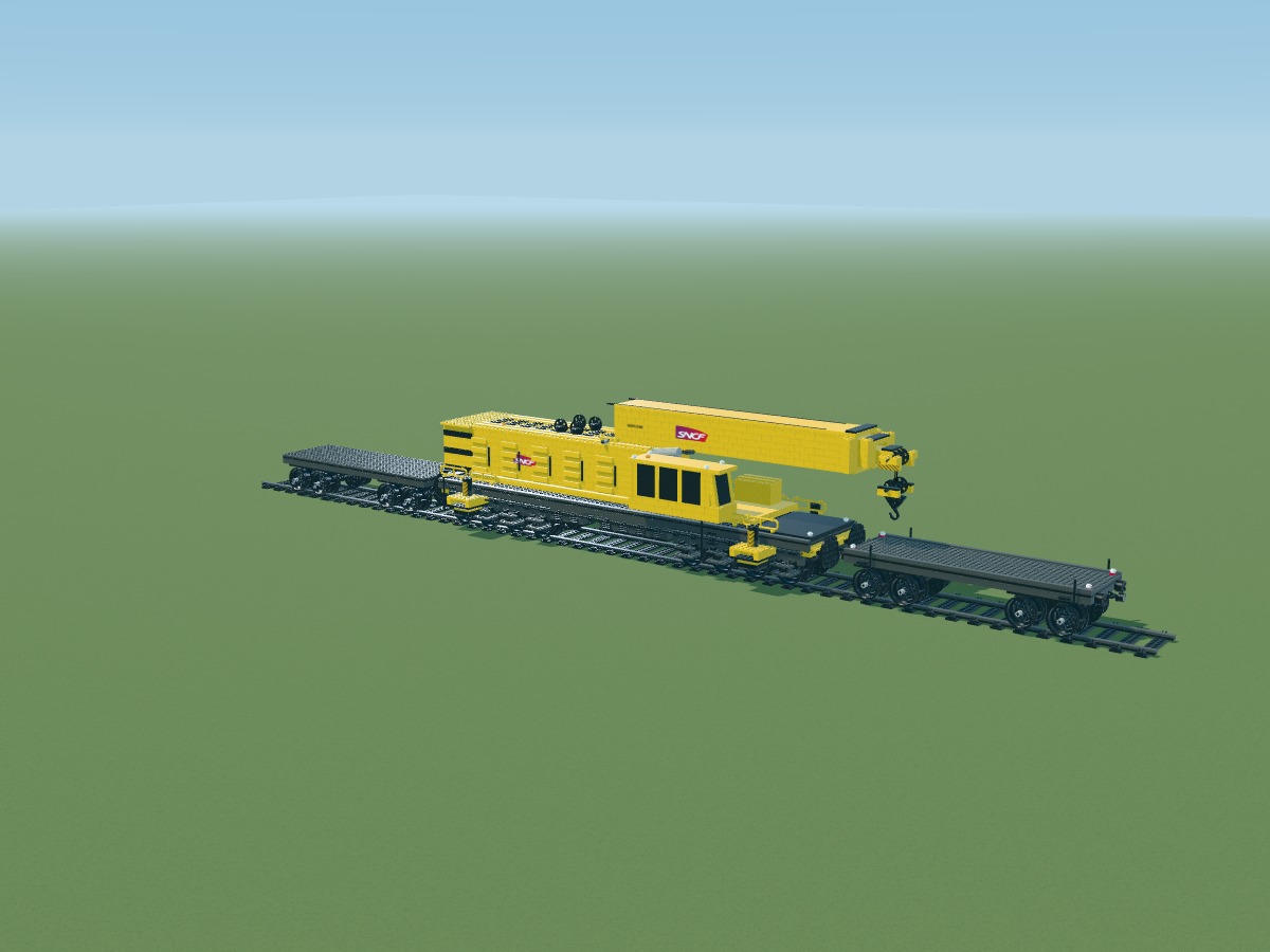
Turn the plates to stagger deck joints. The final strip completes the exact 14-stud width.
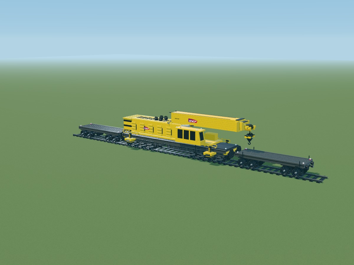
Add smooth deck edges and small end lights. Colors are named in the inventory.
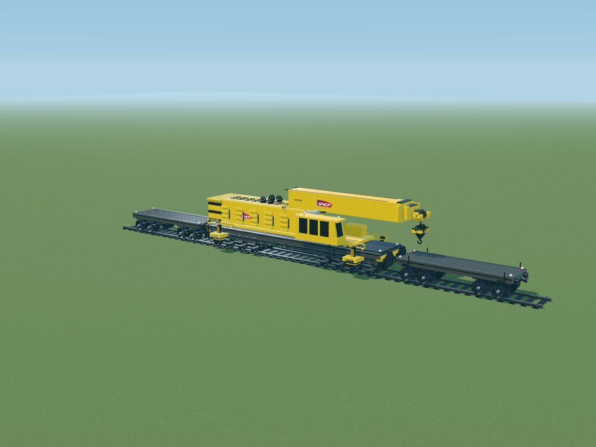
Fit brick-built buffers and couplers at both ends. Coupling the full convoy requires physical validation.
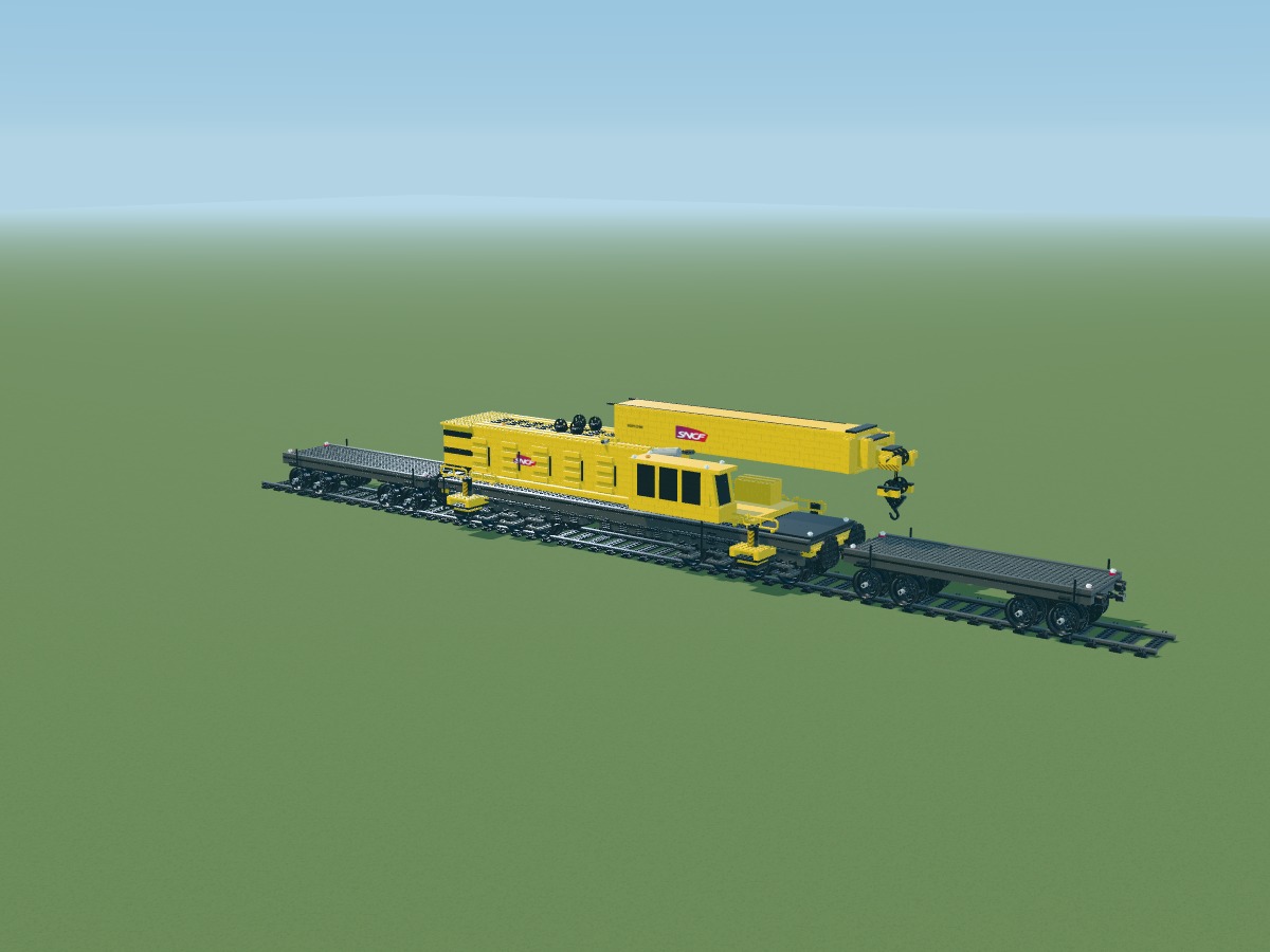
Add small access steps and handholds near the deck ends.
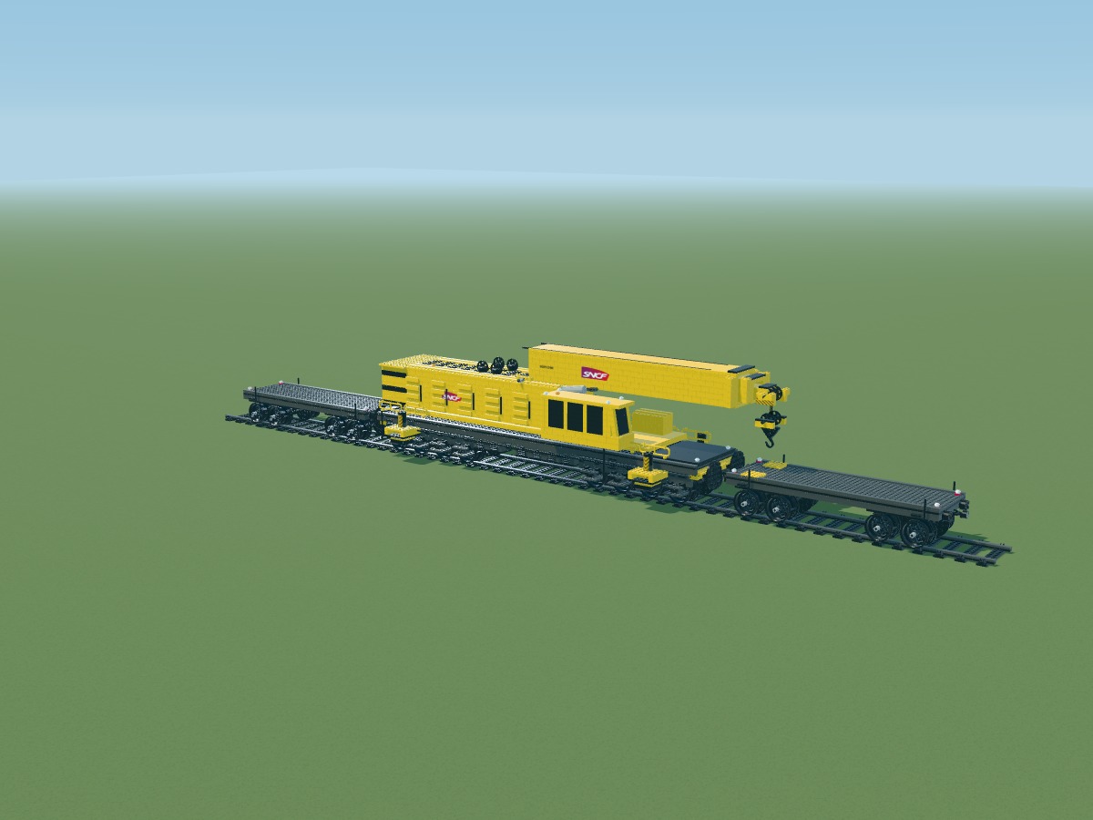
Reinforce the deck edge facing the crane. The cradle rests on plates within the wagon.
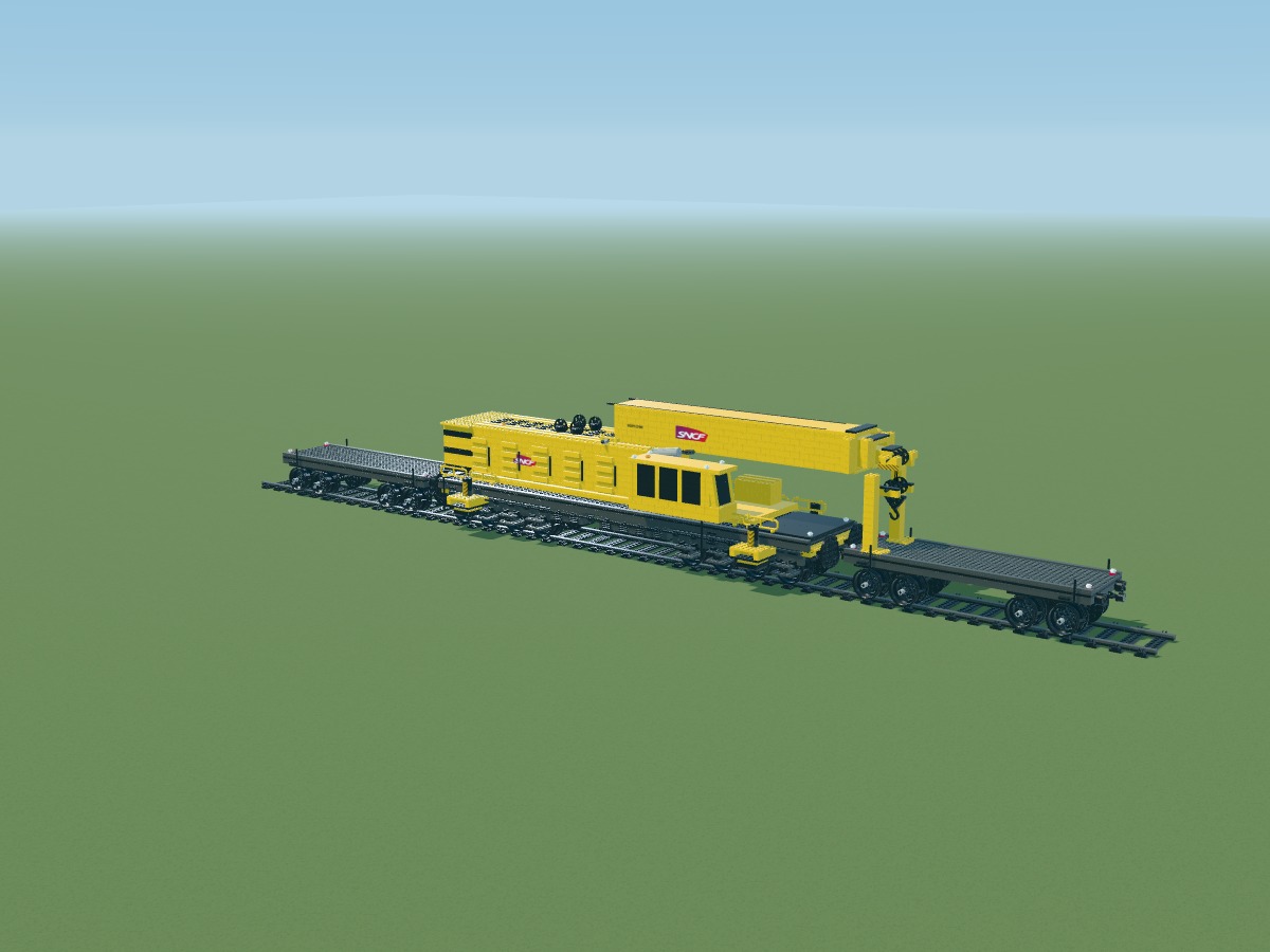
Two yellow uprights carry the cradle beam. Their height follows this study’s transport pose.
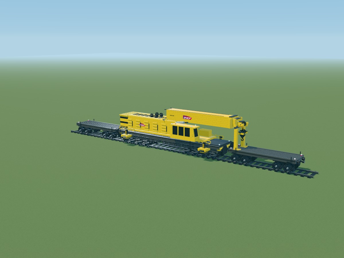
The beam sits on the deck’s first stud row, near X = 53.5. Stud tops reach approximately Y = 24.2; the boom support needs physical testing.
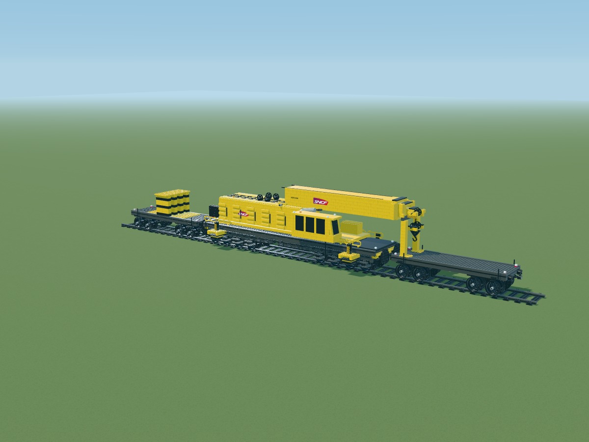
Load beds separate the yellow load from the dark deck. Their layout keeps both wagon ends accessible.
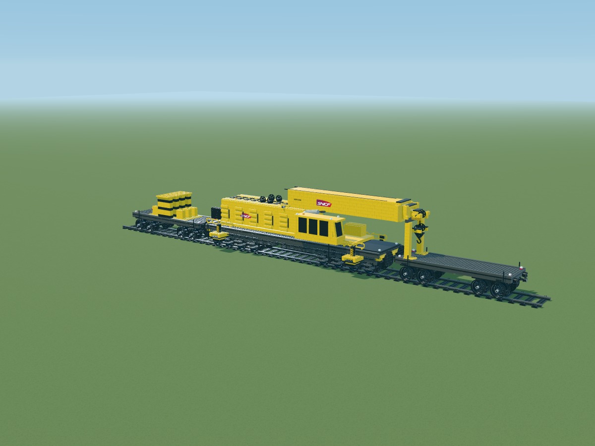
Build two low blocks, separate from the carrier frame. These are model volumes; no lifting mass is claimed.
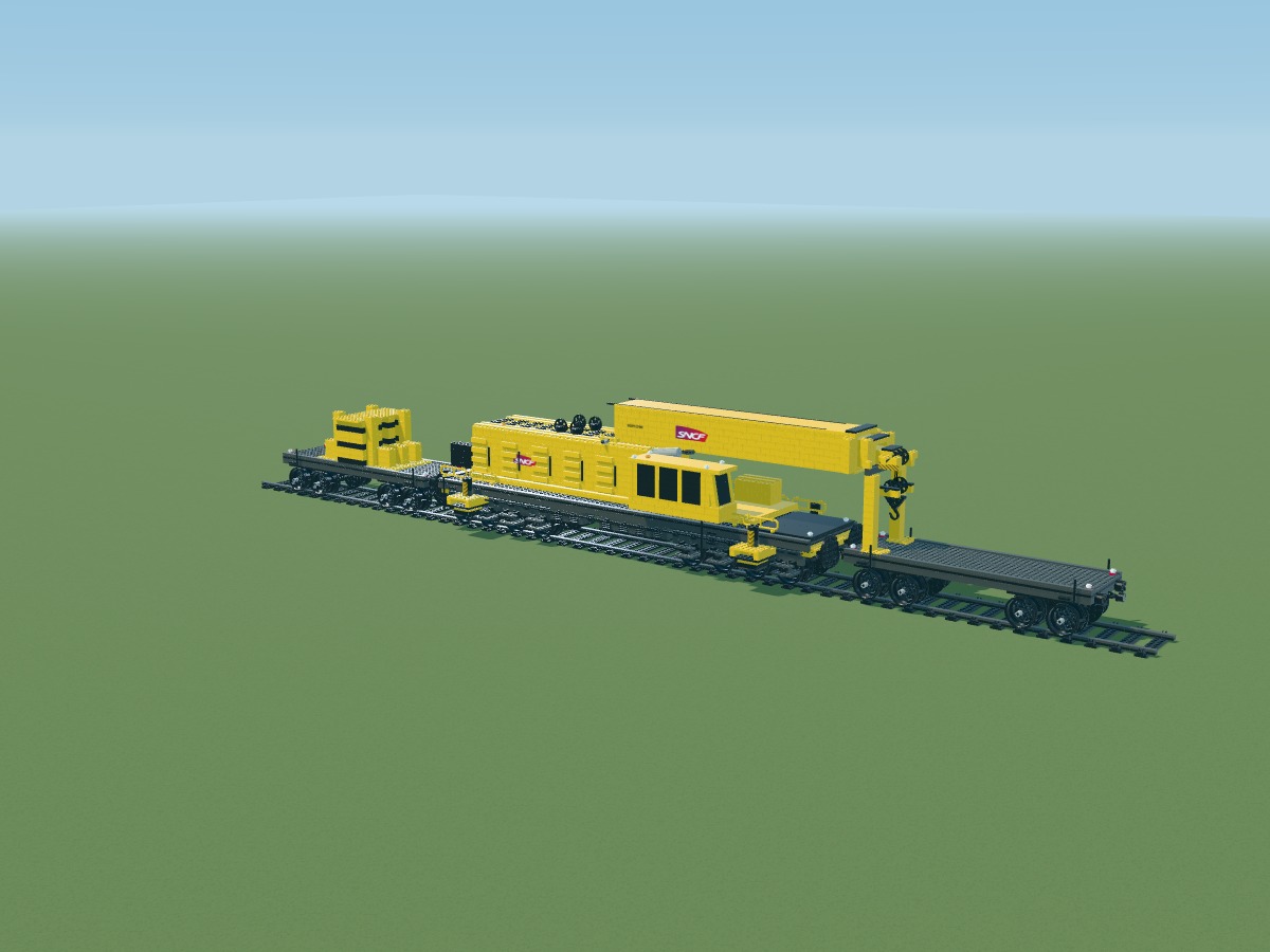
Four uprights form an open central frame, inspired by the load visible in the transport photograph.
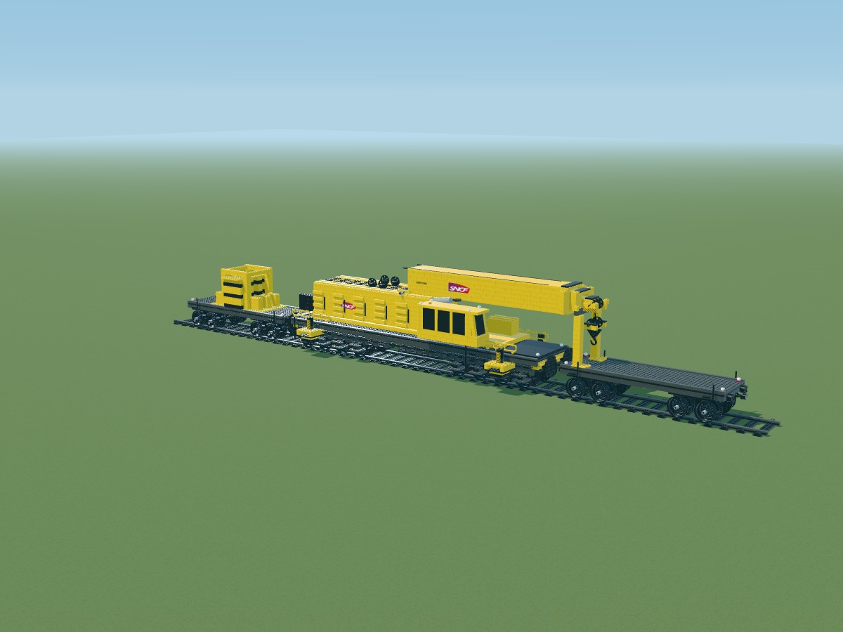
Join the uprights with beams while keeping the centre open. Connections and load restraint still require testing.
Finish with handles and chocks. Transport elements are counted separately from the crane.
This complete inventory includes the crane, both wagons and the display track. Each row represents a part and colour actually present in the digital model. The links document catalogue pieces, not their current availability for purchase.

A JPG image to attach to a message or post on a social network. Add this page’s link to your post or to a Link sticker in your Instagram story.